
Nissan Sentra Service Manual: Removal and installation
Starter motor
Exploded View
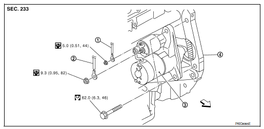
- “S” terminal harness
- “B” terminal harness
- Starter motor
- Cylinder block
Removal and Installation
NOTE:
When removing components such as hoses, tubes/lines, etc., cap or plug openings to prevent fluid from spilling.
REMOVAL
- Disconnect the battery negative terminal. Refer to PG-50, "Removal and Installation (Battery)".
- Remove fan shroud and motor assembly. Refer to CO-17, "Component".
- Remove reservoir hose upper from radiator to water outlet. Refer to CO-15, "Exploded View".
- Remove “B” terminal nut and “B” terminal harness.
- Remove “S” terminal nut and “S” terminal harness.
- Disconnect harness connector from oil temperature sensor. Refer to EM-94, "Exploded View".
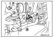
- Disconnect harness connector (1) from crankshaft position sensor.
- Remove harness clip (A) from oil pan (upper), and then remove harness (2) and set aside.
- Remove upper starter motor bolt.
- Remove lower starter motor bolt and remove starter motor.
- Installation is in the reverse order of removal.
- Refill engine coolant. Refer to CO-12, "Changing Engine Coolant".
CAUTION:
- Be careful to tighten "B" terminal nut to the specified torque.
 Symptom diagnosis
Starting system
Symptom table
Symptom
Reference
No normal cranking
Refer to STR-20, "Work Flow (With GR8-1200 NI)" or
STR-24, "Work Flow (Without GR8-1200 NI ...
 Service data and specifications (SDS)
Starter Motor
*: Always check with the Parts Department for the latest parts information. ...
Other materials:
C1130 Engine signal
DTC Logic
DTC DETECTION LOGIC
DTC
Display Item
Malfunction detected condition
Possible causes
C1130
ENGINE SIGNAL 1
When a malfunction is detected in ECM system.
ECM
ABS actuator and electric unit
(control unit)
CAN communication line
...
P0125 ECT Sensor
DTC Logic
DTC DETECTION LOGIC
NOTE:
If DTC P0125 is displayed with P0116, first perform the trouble
diagnosis for DTC P0116. Refer to EC-
196, "DTC Logic".
If DTC P0125 is displayed with P0117 or P0118, first perform the
trouble diagnosis for DTC P0117 or
P0118. Refer to ...
Power supply and ground circuit
A/C AUTO AMP
A/C AUTO AMP. : Diagnosis Procedure
Regarding Wiring Diagram information, refer to HAC-41, "Wiring Diagram".
1.CHECK FUSE
Check fuses [No. 5, 8 and 21, located in the fuse block (J/B)].
NOTE:
Refer to PG-47, "Terminal Arrangement".
Is the inspection result nor ...
