Nissan Sentra Service Manual: Rear seat
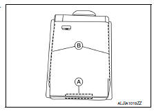
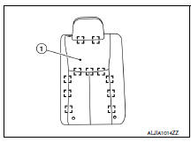
Exploded View
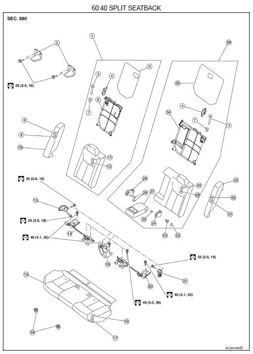
- Rear seatback assembly (rh)
- Seatback striker
- Seatback latch release knob
- Seatback latch assembly
- Seatback silencer (RH)
- Rear seatback frame (rh)
- Seatback latch release knob finisher
- Rear seat bolster trim (RH)
- Rear seat bolster pad (RH)
- Rear seat bolster (rh)
- Seatback trim (rh)
- Seatback pad (rh)
- Seatback hinge bracket (rh)
- LATCH bracket (RH)
- Seat cushion assembly
- Seat cushion hook
- Seat cushion pad
- Seat cushion trim
- Seatback hinge bracket (center)
- Latch bracket (lh)
- Seatback hinge bracket (lh)
- Armrest pivot bolt finisher
- Armrest pivot bolt
- Armrest hinge bracket
- Armrest bushing (lh)
- Armrest bushing (rh)
- Armrest assembly
- Armrest hinge finisher
- Seatback pad (lh)
- Seatback trim (LH)
- Rear seat bolster pad (lh)
- Rear seat bolster trim (lh)
- Rear seat bolster (LH)
- Rear seatback frame (lh)
- Seatback silencer (lh)
- Rear seatback assembly (lh)
Disassembly and Assembly
Seat cushion assembly
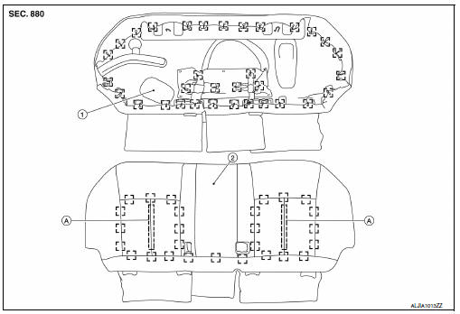
- Seat cushion pad
- Seat cushion trim
- Hook fastener
 Hog ring
Disassembly
- Remove the seat cushion assembly. Refer to se-23, "removal and installation - seat cushion assembly".
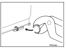
- Remove the hog rings on the bottom side of seat cushion assembly.
Note:
Remove all pieces of hog rings and discard them.
- Remove the hog rings on the top side of seat cushion and separate the seat cushion trim from the seat cushion pad.
Note:
Remove all pieces of hog rings and discard them.
Assembly
Assembly is in the reverse order of disassembly.
Caution:
- Make sure hog rings are correctly fastened around both the seat cushion trim and seat cushion pad wires.
- Replace any deformed or damaged hog rings.
- Make sure any old hog ring pieces are removed from seat.
Note:
- Install new hog rings on the seat cushion trim in original positions.
- Use only one hog ring in each designated location.
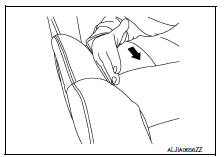
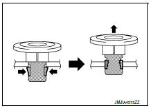
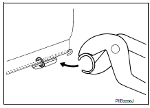
- When installing the seat cushion trim, firmly push down while sliding
your hand along the seams as shown (
 ) to ensure the hook
fasteners below the seat cushion trim are fastened properly.
Rear seatback assembly (rh)
Disassembly
- Remove the rear seatback assembly (rh). Refer to se-23, "removal and installation - 60:40 split seatback".
- Release the j-hook retainer (a) and unzip the seatback trim zippers (b).
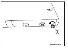
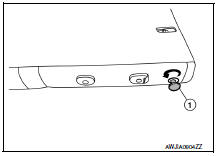
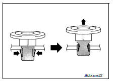
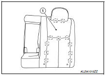
- Rotate the seatback latch release knob (1) counterclockwise and remove.
- Reach up through the seatback pad and remove the seatback latch release knob finisher as shown.
Caution:
Before installing the seatback release knob finisher, check its orientation (front/rear and right/left).
- Remove the seatback trim and seatback pad as an assembly from the rear seatback frame.
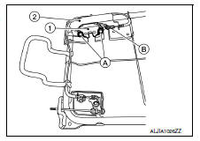
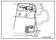
- Release cable end (B) from the seatback latch assembly (1), remove two bolts (A) and the seatback latch assembly from the rear seatback frame (2).
- Remove the hog rings and separate the seatback trim from the seatback pad.
 Hog ring
Note:
Remove all pieces of hog rings and discard them.
Assembly
Assembly is in the reverse order of disassembly.
Caution:
- Make sure hog rings are correctly fastened around both the seatback trim and seatback pad wires.
- Replace any deformed or damaged hog rings.
- Make sure any old hog ring pieces are removed from seat.
Note:
- Install new hog rings on the seatback trim in original positions.
- Use only one hog ring in each designated location.

Rear seatback assembly (lh)
Disassembly
- Remove the rear seatback assembly (LH). Refer to SE-23, "Removal and Installation - 60:40 Split Seatback".
- Remove the armrest assembly. Refer to se-23, "removal and installation - armrest assembly".
- Rotate the seatback latch release knob (1) counterclockwise and remove.
- Reach up through the seatback pad and remove the seatback latch release knob finisher as shown.
Caution:
Before installing the seatback release knob finisher, check its orientation (front/rear and right/left).
- Release the J-clip retainers (A) and remove the seatback trim and seatback pad as an assembly from the rear seatback frame (1).
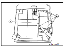
- Release cable end (b) from the seatback latch assembly (1), remove two bolts (a) and the rear seatback latch assembly from the rear seatback frame (2).
- Remove the hog rings and separate the seatback trim from the seatback pad.
 Hog ring
Note:
Remove all pieces of hog rings and discard them.
Assembly
Assembly is in the reverse order of disassembly.
Caution:
- Make sure hog rings are correctly fastened around both the seatback trim and seatback pad wires.
- Replace any deformed or damaged hog rings.
- Make sure any old hog ring pieces are removed from seat.
Note:
- Install new hog rings on the seatback trim in original positions.
- Use only one hog ring in each designated location.
 Front seat
Driver side
DRIVER SIDE : Exploded View
Driver side
Headrest
Headrest holder (locked)
Headrest holder (free)
Seatback silencer
Seatback trim
Seatback pad
Seat belt buckle
S ...

Other materials:
C1716, C1717, C1718, C1719 Transmitter (pressure data)
DTC Logic
NOTE:
The Signal Tech II Tool (J-50190) can be used to perform the following
functions. Refer to the Signal Tech II
User Guide for additional information.
Activate and display TPMS transmitter IDs
Display tire pressure reported by the TPMS transmitter
Read TPMS DTCs
Register ...
Combination meter
Reference Value
VALUES ON THE DIAGNOSIS TOOL
NOTE:
The following table includes information (items) inapplicable to this
vehicle. For information (items) applicable
to this vehicle, refer to CONSULT display items.
Note:
Some items are not available according to vehicle specificat ...
P0846 Transmission fluid pressure SEN/SW B
DTC Logic
DTC DETECTION LOGIC
DTC
CONSULT screen terms
(Trouble diagnosis content)
DTC detection condition
Possible causes
P0846
TRANSMISSION FLUID
PRESSURE SEN/SW B
(Transmission Fluid Pressure
Sensor/Switch B Circuit
Range/Performance)
The detection ...
