
Nissan Sentra Service Manual: Precaution
Precaution for supplemental restraint system (srs) "air bag" and "seat belt pre-tensioner"
The Supplemental Restraint System such as “AIR BAG” and “SEAT BELT PRE-TENSIONER”, used along with a front seat belt, helps to reduce the risk or severity of injury to the driver and front passenger for certain types of collision. Information necessary to service the system safely is included in the SR and SB section of this Service Manual.
Warning:
- To avoid rendering the srs inoperative, which could increase the risk of personal injury or death in the event of a collision which would result in air bag inflation, all maintenance must be performed by an authorized nissan/infiniti dealer.
- Improper maintenance, including incorrect removal and installation of the srs, can lead to personal injury caused by unintentional activation of the system. For removal of spiral cable and air bag module, see the sr section.
- Do not use electrical test equipment on any circuit related to the srs unless instructed to in this service manual. Srs wiring harnesses can be identified by yellow and/or orange harnesses or harness connectors.
Precautions when using power tools (air or electric) and hammers
Warning:
- When working near the airbag diagnosis sensor unit or other airbag system sensors with the ignition on or engine running, do not use air or electric power tools or strike near the sensor(s) with a hammer. Heavy vibration could activate the sensor(s) and deploy the air bag(s), possibly causing serious injury.
- When using air or electric power tools or hammers, always switch the ignition off, disconnect the battery and wait at least three minutes before performing any service.
Precautions for trouble diagnosis
Caution:
Follow the instructions listed below. Failure to do this may cause damage to parts:
- Never apply 7.0 V or more to the measurement terminal.
- Use a tester with open terminal voltage of 7.0 V or less.
- Turn the ignition switch off and disconnect the battery cable from the negative terminal when checking the harness.
Precautions for harness repair
- Solder the repaired area and wrap tape around the soldered area.
Note:
A fray of twisted lines must be within 110 mm (4.33 in).
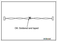
- Bypass connection is never allowed at the repaired area.
Note:
Bypass connection may cause can communication error. The spliced wire becomes separated and the characteristics of twisted line are lost.
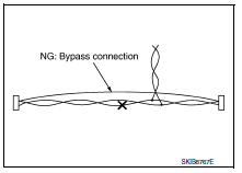
- Replace the applicable harness as an assembly if error is detected on the shield lines of can communication line.
 How to use this manual
How to use this section
Information
“Can” of lan section describes information peculiar to a vehicle and
inspection procedures.
For trouble diagnosis procedure, refer to lan-16, &q ...
 System description
Component parts
Component parts location
ABS actuator and electric unit (control
unit)
Av control unit
A/c auto amp.
Ecm
Ipdm e/r
Tcm
Data link connector
EPS control unit
Bc ...
Other materials:
Main line between ipdm-e and dlc circuit
Diagnosis procedure
1.Check connector
Turn the ignition switch off.
Disconnect the battery cable from the negative terminal.
Check the following terminals and connectors for damage, bend and loose
connection (connector side
and harness side).
Harness connector e4
Harness connec ...
Front suspension assembly
Inspection
COMPONENT PART
Check the mounting conditions (looseness, backlash) of each component. Verify
the component conditions
(wear, damage) are normal.
Ball Joint Axial End Play
Set the front wheels in a straight-ahead position.
Hold the axle side of the transverse link, and check th ...
Power window motor
DRIVER SIDE
DRIVER SIDE : Description
Door glass moves up/down by receiving the signal from main power window and
door lock/unlock switch
DRIVER SIDE : Component Function Check
1. Check front power window motor lh circuit
Check front power window motor lh operation with the main power window ...
