Nissan Sentra Service Manual: Exhaust manifold
Exploded View
CALIFORNIA
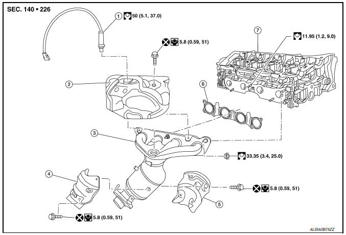
- Air fuel ratio sensor
- Exhaust manifold heat shield (upper)
- Exhaust manifold and three way catalyst
- Exhaust manifold heat shield (rear)
- Exhaust manifold heat shield (front)
- Exhaust manifold gasket
- Cylinder head
EXCEPT CALIFORNIA
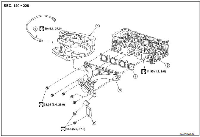
- Air fuel ratio sensor
- Bracket
- Exhaust manifold
- Exhaust manifold gasket
- Cylinder head
- Exhaust manifold heat shield
Removal and Installation
REMOVAL
- Remove the cowl top. Refer to EXT-25, "Exploded View".
- Remove front exhaust tube. Refer to EX-5, "Exploded View".
- Disconnect air fuel ratio sensor harness connector and remove air fuel ratio sensor if necessary.
- Remove exhaust manifold cover.
- Remove exhaust manifold.
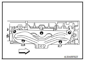
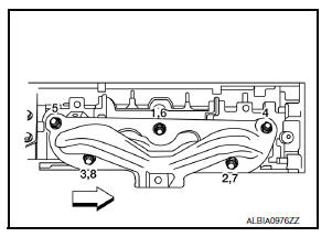
- Loosen nuts in reverse order as shown.
NOTE:
Disregard the numerical order No. 6-8 in removal.
- Remove exhaust manifold gasket.
CAUTION:
Cover engine openings to avoid entry of foreign materials.
INSTALLATION
- Install exhaust manifold gasket (1) to cylinder head as shown.
CAUTION:
Do not reuse exhaust manifold gasket (1).
- Install exhaust manifold with the following procedure:
- Tighten nuts in numerical order as shown.
NOTE:
- Tighten nuts the No.1-3 in two steps.
- The numerical order No.6-8 shows the second step.
- Installation of remaining components is in the reverse order of removal.
Inspection
INSPECTION AFTER REMOVAL
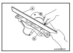
Surface Distortion
- Using feeler gauge (A) and straightedge (B), check the surface distortion of exhaust manifold mating surface in each exhaust port and entire part.
Limit : Refer to EM-119, "Exhaust Manifold".
- If it exceeds the limit, replace exhaust manifold.
 Intake manifold
Exploded View
Clamp
PCV hose
Bracket
Intake manifold gasket
Intake manifold
Mount rubber
Clamp
EVAP hose
EVAP canister purge volume
control solenoid valve
Electric throttl ...
 Oil pan
Exploded View
O-ring
Oil pan (upper)
Oil level gauge guide
O-ring
Oil level gauge
Oil pump drive chain
Crankshaft sprocket
Oil pump sprocket
Oil pump chain tensioner
Oil pump
...
Other materials:
Door lock actuator
Driver side
Driver side : component function check
1.CHECK FUNCTION
Select DOOR LOCK of BCM using CONSULT.
Select DOOR LOCK in ACTIVE TEST mode.
Touch ALL LOCK or ALL UNLK to check that it works normally.
Is the inspection result normal?
YES >> Door lock actuator is OK.
NO > ...
Fuel injector and fuel tube
Exploded View
Bracket
Fuel tube bracket
Fuel feed tube
Quick connector cap
Fuel tube
O-ring (black)
Fuel injector
O-ring (green)
Injector clip
CAUTION:
Do not remove or disassemble parts unless instructed.
Removal and Installation
WARNING:
Put a “CAUTION: FLAM ...
Ecu diagnosis information
Audio unit
Reference value
TERMINAL LAYOUT
PHYSICAL VALUES
Bose speaker amp
Reference value
TERMINAL LAYOUT
PHYSICAL VALUES
BluetoothВ® control unit
Reference value
TERMINAL LAYOUT
PHYSICAL VALUES
...
