Nissan Sentra Service Manual: Basic inspection
Diagnosis and repair work flow
Work Flow
OVERALL SEQUENCE
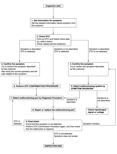
DETAILED FLOW
1.GET INFORMATION FOR SYMPTOM
- Get detailed information from the customer about the symptom (the condition and the environment when the incident/malfunction occurs).
- Check operation condition of the function that is malfunctioning.
>> GO TO 2.
2.CHECK DTC
- Check DTC.
- Perform the following procedure if DTC is detected.
- Record DTC and freeze frame data (Print them out using CONSULT.)
- Erase DTC.
- Study the relationship between the cause detected by DTC and the symptom described by the customer.
- Check related service bulletins for information.
Are any symptoms described and any DTC detected? Symptom is described, DTC is detected>>GO TO 3.
Symptom is described, DTC is not detected>>GO TO 4.
Symptom is not described, DTC is detected>>GO TO 5.
3.CONFIRM THE SYMPTOM
Try to confirm the symptom described by the customer.
Also study the normal operation and fail-safe related to the symptom.
Verify relation between the symptom and the condition when the symptom is detected.
>> GO TO 5.
4.CONFIRM THE SYMPTOM
Try to confirm the symptom described by the customer.
Verify relation between the symptom and the condition when the symptom is detected.
>> GO TO 6.
5.PERFORM DTC CONFIRMATION PROCEDURE
Perform DTC CONFIRMATION PROCEDURE for the detected DTC, and then check that DTC is detected again. At this time, always connect CONSULT to the vehicle, and check self diagnostic results in real time.
If two or more DTCs are detected, refer to BCS-108, "DTC Inspection Priority Chart" and determine trouble diagnosis order.
NOTE:
- Freeze frame data is useful if the DTC is not detected.
- Perform Component Function Check if DTC CONFIRMATION PROCEDURE is not included on Service Manual. This simplified check procedure is an effective alternative though DTC cannot be detected during this check.
If the result of Component Function Check is NG, it is the same as the detection of DTC by DTC CONFIRMATION PROCEDURE.
Is DTC detected? YES >> GO TO 7.
NO >> Check according to GI-39, "Intermittent Incident".
6.DETECT MALFUNCTIONING SYSTEM BY SYMPTOM DIAGNOSIS
Detect malfunctioning system according to SYMPTOM DIAGNOSIS based on the confirmed symptom in step 4, and determine the trouble diagnosis order based on possible causes and symptom.
Is the symptom described? YES >> GO TO 7.
NO >> Monitor input data from related sensors or check voltage of related module terminals using CONSULT.
7.DETECT MALFUNCTIONING PART BY DIAGNOSIS PROCEDURE
Inspect according to Diagnosis Procedure of the system.
Is malfunctioning part detected? YES >> GO TO 8.
NO >> Check according to GI-39, "Intermittent Incident".
8.REPAIR OR REPLACE THE MALFUNCTIONING PART
- Repair or replace the malfunctioning part.
- Reconnect parts or connectors disconnected during Diagnosis Procedure again after repair and replacement.
- Check DTC. If DTC is detected, erase it.
>> GO TO 9.
9.FINAL CHECK
When DTC is detected in step 2, perform DTC CONFIRMATION PROCEDURE again, and then check that the malfunction is repaired securely.
When symptom is described by the customer, refer to confirmed symptom in step 3 or 4, and check that the symptom is not detected.
Is DTC detected and does symptom remain? YES-1 >> DTC is detected: GO TO 7.
YES-2 >> Symptom remains: GO TO 4.
NO >> Before returning the vehicle to the customer, always erase DTC.
Keyfob id registration
Description
Perform the following procedure after BCM is replaced or when new keyfob ID is registered
NOTE:
When registering the keyfob ID, perform only one procedure to simultaneously register both ID (IMMOBILIZER ID and keyfob ID).
Work procedure
1.STEP 1
Close all doors.
>> GO TO 2.
2.STEP 2
Preform lock operation by door lock and unlock switch.
>> GO TO 3.
3.STEP 3
- Remove and insert the key into the ignition key cylinder 6 times within 10 seconds (turning the key switch from OFF to ON counts as 1 time).
- All doors unlock automatically.
NOTE:
On the sixth key insertion, keep the key in the ignition key cylinder with the key switch ON.
Do all unlock automatically? YES >> GO TO 4.
NO >> GO TO 1.
4.STEP 4
Turn ignition switch to ACC within 3 seconds after all doors unlock and perform lock operation by door lock and unlock switch.
>> GO TO 5.
5.STEP 5
- Press the lock or unlock button of the keyfob to be added.
- All doors unlock simultaneously.
- Key ID is registered.
Is key ID registered? YES-1 >> When adding a keyfob: GO TO 6.
YES-2 >> When ending registration: GO TO 8.
NO >> GO TO 1.
6.STEP 6
Preform lock operation by door lock and unlock switch.
>> GO TO 7.
7.STEP 7
- Press the lock or unlock button of the keyfob to be added.
- All doors unlock simultaneously.
- Key ID is registered.
Is key ID registered? YES-1 >> When adding a keyfob: GO TO 6.
YES-2 >> When ending registration: GO TO 8.
NO >> GO TO 6.
8.STEP 8
Open the driver door.
>> REGISTRATION END
 Wiring diagram
Remote keyless entry system
Wiring diagram
Power door lock system
Wiring Diagram
Trunk lid opener
Wiring diagram
...
 DTC/circuit diagnosis
U1000 can comm
Description
Refer to LAN-7, "CAN COMMUNICATION SYSTEM : System Description".
Dtc logic
DTC DETECTION LOGIC
NOTE:
U1000 can be set if a module harness was disconnected ...
Other materials:
Cleaning
If your windshield is not clear after using the
windshield washer or if a wiper blade chatters
when running, wax or other material may be on
the blade or windshield.
Clean the outside of the windshield with a washer
fluid or a mild detergent. Your windshield is clean
if beads do not form whe ...
Towing your vehicle
When towing your vehicle, all State (Provincial in
Canada) and local regulations for towing must be
followed. Incorrect towing equipment could damage
your vehicle. Towing instructions are available
from a NISSAN dealer. Local service operators
are generally familiar with the applicable laws
an ...
Forward-facing child restraint installation using LATCH
Refer to all Warnings and Cautions in the “Child
safety” and “Child restraints” sections before installing
a child restraint.
Follow these steps to install a forward-facing
child restraint using the LATCH system:
Position the child restraint on the seat. Always
follow the child r ...
