Nissan Sentra Service Manual: Power window main switch
Reference Value
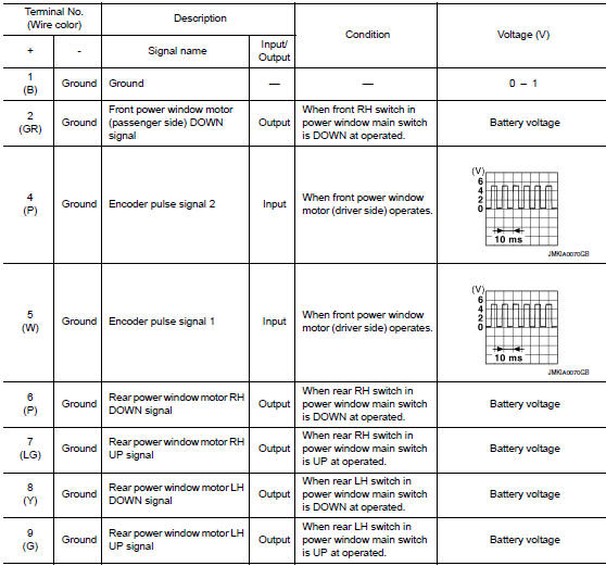
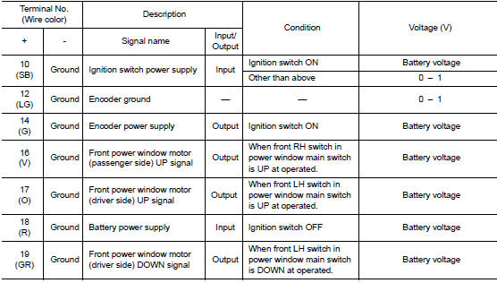
TERMINAL LAYOUT
PHYSICAL VALUES
MAIN POWER WINDOW AND DOOR LOCK/UNLOCK SWITCH
Fail Safe
FAIL-SAFE CONTROL
Switches to fail-safe control when malfunction is detected in encoder signal that detects up/down speed and direction of door glass. Switches to fail-safe control when error beyond regulation value is detected between the fully closed position and the actual position of the glass.
| Error | Error condition |
| Pulse sensor malfunction | When only one side of pulse signal is being detected for more than the specified value. |
| Both pulse sensors malfunction | When both pulse signals have not been detected for more than the specified value during glass open/close operation. |
| Pulse direction malfunction | When the pulse signal that is detected during glass open/close operation detects the opposite condition of power window motor operating direction. |
| Glass recognition position malfunction 1 | When it detects the error between glass fully closed position in power window switch memory and actual fully closed position during glass open/close operation is more than the specified value. |
| Glass recognition position malfunction 2 | When it detects pulse count more than the value of glass full stroke during glass open/close operation. |
It changes to condition before initialization and the following functions do not operate when switched to failsafe control.
- Auto-up operation
- Anti-pinch function
Perform initial operation to recover when switched to fail-safe mode. However, it switches back to fail-safe control when malfunction is found in power window main switch or front power window motor (driver side).
 BCM(body control module)
List of ECU Reference
WITH INTELLIGENT KEY SYSTEM
WITHOUT INTELLIGENT KEY SYSTEM
...
 Wiring diagram
Power window system
Wiring Diagram
...
Other materials:
Cooler pipe and hose
Exploded view
High-pressure service port
High-pressure pipe
Expansion valve
Low-pressure service port
Low-pressure flexible hose
Compressor
Refrigerant pressure sensor
Condenser and liquid tank assembly
High-pressure flexible hose
Low-pressure flexible hose
Low-pressure f ...
Component parts
Engine control system
ENGINE CONTROL SYSTEM :Component Parts Location
Engine room compartment
No.
Component
Function
1
IPDM E/R
IPDM E/R control the internal relays and the actuators.
When CAN communication with ECM is impossible, IPDM
E/R performs fail-sa ...
Starting system (with intelligent key)
Wiring Diagram
...
