Nissan Sentra Service Manual: Parking brake switch
Component Function Check
1.CHECK PARKING BRAKE SWITCH OPERATION
Check that brake warning lamp in combination meter turns ON/OFF when parking brake is actuated.
Is the inspection result normal? YES >> Inspection End.
NO >> Proceed to diagnosis procedure. Refer to BRC-90, "Diagnosis Procedure".
Diagnosis Procedure
Regarding Wiring Diagram information, refer to BRC-44, "Wiring Diagram".
1.CONNECTOR INSPECTION
-
Turn ignition switch OFF.
-
Disconnect combination meter and parking brake switch connectors.
-
Check connectors and terminals for deformation, disconnection, looseness or damage.
Is the inspection result normal? YES >> GO TO 2.
NO >> Repair or replace as necessary.
2.CHECK PARKING BRAKE SWITCH
Check parking brake switch. Refer to BRC-91, "Component Inspection".
Is the inspection result normal? YES >> GO TO 3.
NO >> Replace parking brake switch. Refer to PB-7, "Exploded View".
3.Check parking brake switch signal
 With CONSULT.
-
Connect combination meter connector and parking brake switch connectors.
-
Turn ignition switch ON.
-
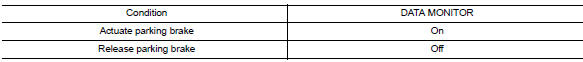
In “DATA MONITOR” select “PARK BRAKE SW” and check parking brake switch signal.
Is the inspection result normal? YES >> Refer to BRC-51, "Work Flow".
NO >> GO TO 4.
4.Check parking brake switch circuit
-
Turn ignition switch OFF.
-
Disconnect combination meter and parking brake switch connectors.
-
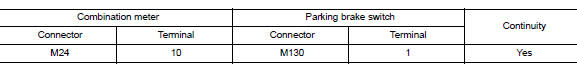
Check continuity between combination meter connector M24 terminal 10 and parking brake switch connector M130 terminal 1.
-
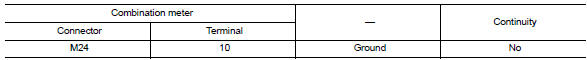
Check continuity between combination meter connector and ground.
Is the inspection result normal? YES >> Replace combination meter. Refer to MWI-77, "Removal and Installation".
NO >> Repair or replace malfunctioning components.
Component Inspection
1.Check parking brake switch
-
Turn ignition switch OFF.
-
Disconnect parking brake switch connector.
-
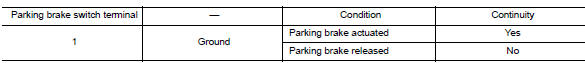
Check continuity between parking brake switch terminal 1 and ground.
Is the inspection result normal? YES >> Inspection End.
NO >> Replace parking brake switch. Refer to PB-7, "Exploded View".
 U1010 Control unit (CAN)
Description
Initial diagnosis of ABS actuator and electric unit (control
unit)
DTC Logic
DTC DETECTION LOGIC
DTC
Items
(CONSULT screen terms)
DTC detection condition
Possible ...
 VDC OFF Switch
Component Function Check
1.CHECK VDC OFF SWITCH OPERATION
Check that VDC OFF indicator lamp in combination meter turns
ON/OFF when VDC OFF switch is operated.
Is the inspection result normal?
...
Other materials:
Rear drum brake
BRAKE LINING
BRAKE LINING : Inspection
INSPECTION
Brake Lining
Check brake lining wear thickness (A). Check using a scale if
necessary.
Lining wear thickness (A) : Refer to BR-55, "Rear
Drum Brake".
BRAKE DRUM
BRAKE DRUM : Inspection
INSPECTION
Appearance
Check surfac ...
L terminal circuit (open)
Description
The “L” terminal circuit controls the charge warning lamp. The charge warning
lamp turns ON when the ignition
switch is set to ON or START. When the generator is providing sufficient voltage
with the engine running,
the charge warning lamp turns OFF. If the charge warnin ...
Break-in schedule
CAUTION
During the first 1,200 miles (2,000 km),
follow these recommendations to obtain
maximum engine performance and ensure
the future reliability and economy of your
new vehicle. Failure to follow these recommendations
may result in shortened
engine life and reduced engine
performance.
A ...
