Nissan Sentra Service Manual: P2100, P2103 Throttle control motorrelay
DTC Logic
DTC DETECTION LOGIC
| DTC No. | CONSULT screen terms (Trouble diagnosis content) | DTC detecting condition | Possible cause |
| P2100 | ETC MOT PWR-B1 (Throttle actuator “A” control motor circuit/ open) | ECM detects a voltage of power source for throttle control motor is excessively low. |
|
| P2103 | ETC MOT PWR (Throttle actuator “A” control motor circuit high) | ECM detect the throttle control motor relay is stuck ON. |
|
DTC CONFIRMATION PROCEDURE
1.PRECONDITIONING
If DTC Confirmation Procedure has been previously conducted, always perform the following procedure before conducting the next test.
- Turn ignition switch OFF and wait at least 10 seconds.
- Turn ignition switch ON.
- Turn ignition switch OFF and wait at least 10 seconds.
TESTING CONDITION:
Before performing the following procedure, confirm that battery voltage is more than 8 V.
Witch DTC is detected? P2100 >> GO TO 2.
P2103 >> GO TO 3.
2.PERFORM DTC CONFIRMATION PROCEDURE FOR DTC P2100
- Turn ignition switch ON and wait at least 2 seconds.
- Start engine and let it idle for 5 seconds
- Check DTC.
Is DTC detected? YES >> Proceed to EC-423, "Diagnosis Procedure".
NO >> INSPECTION END
3.PERFORM DTC CONFIRMATION PROCEDURE FOR DTC P2103
- Turn ignition switch ON and wait at least 1 second.
- Check DTC.
Is DTC detected? YES >> Proceed to EC-423, "Diagnosis Procedure".
NO >> INSPECTION END
Diagnosis Procedure
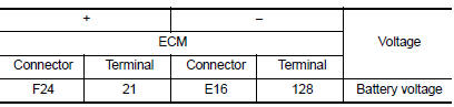
1.CHECK THROTTLE CONTROL MOTOR RELAY POWER SUPPLY
- Turn ignition switch OFF.
- Check the voltage between ECM harness connector and ground.
Is the inspection result normal? YES >> GO TO 3.
NO >> GO TO 2.
2.CHECK THROTTLE CONTROL MOTOR RELAY POWER SUPPLY CIRCUIT
Disconnect ECM harness connector.
Disconnect IPDM E/R harness connector.
Check the continuity between ECM harness connector and IPDM E/R harness connector.
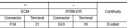
- Also check harness for short to ground.
Is the inspection result normal? YES >> Perform the trouble diagnosis for power supply circuit.
NO >> Repair or replace error-detected parts.
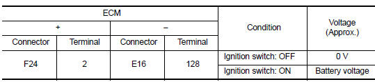
3.CHECK THROTTLE CONTROL MOTOR RELAY INPUT SIGNAL
Check the voltage between ECM harness connector and ground as per the following conditions.
Is the inspection result normal? YES >> Check intermittent incident. Refer to GI-39, "Intermittent Incident".
NO >> GO TO 4.
4.CHECK THROTTLE CONTROL MOTOR RELAY INPUT SIGNAL CIRCUIT
- Turn ignition switch OFF.
- Disconnect ECM harness connector.
- Disconnect IPDM E/R harness connector.
- Check the continuity between ECM harness connector and IPDM E/R harness connector.
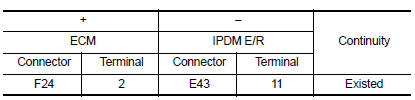
- Also check harness for short to ground and to power.
Is the inspection result normal? YES >> Check intermittent incident. Refer to GI-39, "Intermittent Incident".
NO >> Repair or replace error-detected parts.
 P2096, P2097 A/F Sensor 1
DTC Logic
DTC DETECTION LOGIC
DTC No.
CONSULT screen terms
(Trouble diagnosis content)
DTC detecting condition
Possible Cause
P2096
POST CAT FUEL TRIM SYS B1
(Post ...
 P2101 Electric throttle control function
DTC Logic
DTC DETECTION LOGIC
NOTE:
If DTC P2101 is displayed with DTC P2100, first perform the trouble
diagnosis for DTC P2100. Refer
to EC-423, "DTC Logic".
If DTC P2101 is di ...
Other materials:
P0340 CMP Sensor (PHASE)
DTC Logic
DTC DETECTION LOGIC
DTC No.
CONSULT screen terms
(Trouble diagnosis content)
DTC detecting condition
Possible cause
P0340
CMP SEN/CIRC-B1
(Camshaft position sensor
“A” circuit bank 1)
The cylinder No. signal is not sent to ECM fo ...
P0111 IAT Sensor
DTC Logic
DTC DETECTION LOGIC
DTC No.
CONSULT screen terms
(Trouble diagnosis content)
DTC detecting condition
Possible cause
P0111
IAT SENSOR 1 B1
(Intake air temperature sensor 1
circuit range/performance bank 1)
The comparison result of signals transmitte ...
S terminal circuit
Description
The output voltage of the generator is controlled by the IC regulator at
terminal “S” detecting the input voltage
from battery.
The “S” terminal circuit detects the battery voltage to adjust the generator
output voltage with the IC voltage
regulator.
Diagn ...
