Nissan Sentra Service Manual: P1078 EVT Control position sensor
DTC Logic
DTC DETECTION LOGIC
| DTC No. | CONSULT screen terms (Trouble diagnosis content) | DTC detecting condition | Possible cause |
| P1078 | EXH TIM SEN/CIRC-B1 (Exhaust valve timing control position sensor circuit bank 1) | An excessively high or low voltage from the sensor is sent to ECM. |
|
DTC CONFIRMATION PROCEDURE
1.PRECONDITIONING
If DTC Confirmation Procedure has been previously conducted, always perform the following procedure before conducting the next test.
- Turn ignition switch OFF and wait at least 10 seconds.
- Turn ignition switch ON.
- Turn ignition switch OFF and wait at least 10 seconds.
>> GO TO 2.
2.PERFORM DTC CONFIRMATION PROCEDURE
- Start engine and let it idle for 10 seconds.
- Check 1st trip DTC.
Is 1st trip DTC detected? YES >> Proceed to EC-359, "Diagnosis Procedure".
NO >> INSPECTION END
Diagnosis Procedure
1.CHECK EXHAUST VALVE TIMING (EVT) CONTROL POSITION SENSOR POWER SUPPLY
- Turn ignition switch OFF.
- Disconnect exhaust valve timing (EVT) control position sensor harness connector.
- Turn ignition switch ON.
- Check the voltage between EVT control position sensor harness connector and ground.
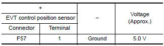
Is the inspection result normal? YES >> GO TO 3.
NO >> GO TO 2.
2.CHECK SENSOR POWER SUPPLY 2 CIRCUIT
Check sensor power supply 2 circuit. Refer to EC-444, "Diagnosis Procedure".
Is inspection result normal? YES >> Perform the trouble diagnosis for power supply circuit.
NO >> Repair or replace error-detected parts.
3.CHECK EVT CONTROL POSITION SENSOR GROUND CIRCUIT
- Turn ignition switch OFF.
- Disconnect ECM harness connector
- Check the continuity between EVT control position sensor harness connector and ECM harness connector.
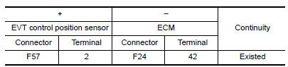
- Also check harness for short to power.
Is the inspection result normal? YES >> GO TO 4.
NO >> Repair or replace error-detected parts.
4.CHECK EVT CONTROL POSITION SENSOR INPUT SIGNAL CIRCUIT
- Disconnect ECM harness connector.
- Check the continuity between EVT control position sensor harness connector and ECM harness connector.
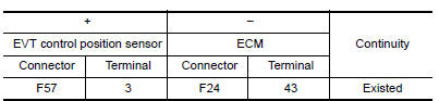
- Also check harness for short to ground and to power.
Is the inspection result normal? YES >> GO TO 5.
NO >> Repair or replace error-detected parts.
5.CHECK EVT CONTROL POSITION SENSOR
Check the EVT control position sensor. Refer to EC-360, "Component Inspection (EVT Control Position Sensor)".
Is the inspection result normal? YES >> GO TO 6.
NO >> Replace EVT control position sensor. Refer to EM-60, "Removal and Installation".
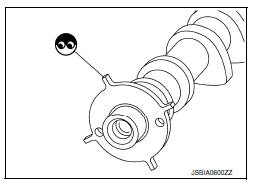
6.CHECK CAMSHAFT (EXT)
Check the following.
- Accumulation of debris to the signal plate of camshaft rear end
- Chipping signal plate of camshaft rear end
Is the inspection result normal? YES >> Check intermittent incident. Refer to GI-39, "Intermittent Incident".
NO >> Remove debris and clean the signal plate of camshaft rear end or replace camshaft. Refer to EM-60, "Removal and Installation".
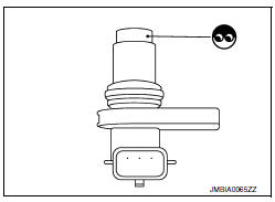
Component Inspection (EVT Control Position Sensor)
1.EXHAUST VALVE TIMING (EVT) CONTROL POSITION SENSOR-1
- Turn ignition switch OFF.
- Disconnect EVT control position sensor harness connector.
- Loosen the fixing bolt of the sensor.
- Remove EVT control position sensor.
- Visually check the sensor for chipping.
Is the inspection result normal? YES >> GO TO 2.
NO >> Replace EVT control position sensor. Refer to EM-60, "Removal and Installation".
2.EVT CONTROL POSITION SENSOR-2
Check resistance EVT control position sensor terminals as shown below.
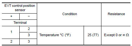
Is the inspection result normal? YES >> INSPECTION END
NO >> Replace EVT control position sensor. Refer to EM-60, "Removal and Installation".
 P0850 PNP Switch
Description
For CVT models, transmission range switch is turn ON when the selector lever
is P or N.
For M/T models, park/neutral position (PNP) range switch is ON when the selector
lever is Ne ...
 P1148 Closed loop control
DTC Logic
DTC DETECTION LOGIC
NOTE:
DTC P1148 is displayed with DTC for A/F sensor 1.
When the DTC is detected, perform the trouble diagnosis of DTC corresponding to
A/F sensor 1.
DTC ...
Other materials:
Precaution for work
When removing or disassembling each component, be careful not to damage
or deform it. If a component
may be subject to interference, be sure to protect it with a shop cloth.
When removing (disengaging) components with a screwdriver or similar
tool, be sure to wrap the component
with a ...
Inspection and adjustment
Additional service when replacing control unit
Additional service when replacing control unit : description
Memory reset procedure
Please observe the following instructions at confirming the moonroof
operation.
Note:
Do not disconnect the electronic power while the moonroof is operating ...
P0138 HO2S2
DTC Logic
DTC DETECTION LOGIC
The heated oxygen sensor 2 has a much longer switching time between rich and
lean than the air fuel ratio (A/
F) sensor 1. The oxygen storage capacity of the three way catalyst (manifold)
causes the longer switching
time.
MALFUNCTION A
To judge the malfunction ...
