Nissan Sentra Service Manual: P0643 Sensor power supply
Description
ECM supplies a voltage of 5.0 V to some of the sensors systematically divided into 2 groups, respectively.
Accordingly, when a short circuit develops in a sensor power source, a malfunction may occur simultaneously in the sensors belonging to the same group as the shorted-circuit sensor.
Sensor power supply 1
- Battery current sensor
- Crankshaft position (CKP) sensor (POS)
- Throttle position (TP) sensor
- Accelerator pedal position (APP) sensor 1
NOTE:
If sensor power supply 1 circuit is malfunctioning, DTC P0643 is displayed.
Sensor power supply 2
- Camshaft position (CMP) sensor (PHASE)
- Mass air flow (MAF) sensor
- Engine oil pressure (EOP) sensor
- Exhaust valve timing (EVT) control position sensor
- Accelerator pedal position (APP) sensor 2
- Intake manifold runner control valve position sensor
DTC Logic
DTC DETECTION LOGIC
| DTC No. | CONSULT screen terms (Trouble diagnosis content) | DTC detecting condition | Possible cause |
| P0643 | SENSOR POWER/CIRC (Sensor reference voltage ″A″ circuit high) | ECM detects that the voltage of sensor power supply 1 is excessively low or high. |
|
DTC CONFIRMATION PROCEDURE
1.PRECONDITIONING
If DTC Confirmation Procedure has been previously conducted, always perform the following procedure before conducting the next test.
- Turn ignition switch OFF and wait at least 10 seconds.
- Turn ignition switch ON.
- Turn ignition switch OFF and wait at least 10 seconds.
TESTING CONDITION:
Before performing the following procedure, confirm that battery voltage is more than 10 V at idle.
>> GO TO 2.
2.PERFORM DTC CONFIRMATION PROCEDUR
- Start engine and let it idle for 1 second.
- Check DTC.
Is DTC detected? YES >> Refer to EC-354, "Diagnosis Procedure".
NO >> INSPECTION END
Diagnosis Procedure
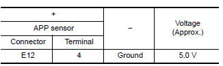
1.CHECK ACCELERATOR PEDAL POSITION SENSOR 1 POWER SUPPLY CIRCUIT
- Disconnect accelerator pedal position (APP) sensor harness connector.
- Turn ignition switch ON.
- Check the voltage between APP sensor harness connector and ground.
Is the inspection result normal? YES >> GO TO 4.
NO >> GO TO 2.
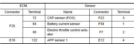
2.CHECK SENSOR POWER SUPPLY CIRCUITS
Check harness for short to power and short to ground, between the following terminals.
Is the inspection result normal? YES >> GO TO 3.
NO >> Repair short to ground or short to power in harness or connectors.
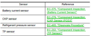
3.CHECK COMPONENTS
Check the following.
Is the inspection result normal? YES >> GO TO 4.
NO >> Repair or replace malfunctioning component.
4.CHECK APP SENSOR
Check APP sensor. Refer to EC-433, "Component Inspection (APP Sensor)".
Is the inspection result normal? YES >> Check intermittent incident. Refer to GI-39, "Intermittent Incident".
NO >> Replace accelerator pedal assembly. Refer to ACC-3, "Removal and Installation".
 P060B ECM
DTC Logic
DTC DETECTION LOGIC
DTC No.
CONSULT screen terms
(Trouble diagnosis content)
DTC detecting condition
Possible cause
P060B
CONTROL MODULE
(Internal control ...
 P0850 PNP Switch
Description
For CVT models, transmission range switch is turn ON when the selector lever
is P or N.
For M/T models, park/neutral position (PNP) range switch is ON when the selector
lever is Ne ...
Other materials:
Diagnosis system (BCM)
Common item
Common item : consult function (bcm - common item)
Application item
Consult performs the following functions via can communication with bcm.
System application
Bcm can perform the following functions.
Intelligent key
Intelligent key : consult function (bcm - intelligent ke ...
Service equipment
RECOVERY/RECYCLING RECHARGING EQUIPMENT
Be certain to follow the manufacturer’s instructions for machine operation
and machine maintenance. Do not
introduce any refrigerant other than that specified into the machine.
ELECTRICAL LEAK DETECTOR
Be certain to follow the manufacturer’s ...
Can communication circuit
Diagnosis procedure
1.Connector inspection
Turn the ignition switch off.
Disconnect the battery cable from the negative terminal.
Disconnect all the unit connectors on CAN communication system.
Check terminals and connectors for damage, bend and loose connection.
Is the inspection resu ...
