Nissan Sentra Service Manual: Can communication circuit
Diagnosis procedure
1.Connector inspection
- Turn the ignition switch off.
- Disconnect the battery cable from the negative terminal.
- Disconnect all the unit connectors on CAN communication system.
- Check terminals and connectors for damage, bend and loose connection.
Is the inspection result normal? Yes >> go to 2.
No >> repair the terminal and connector.
2.Check harness continuity (short circuit)
Check the continuity between the data link connector terminals.
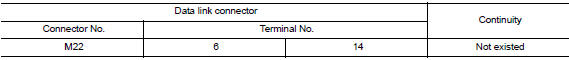
Is the inspection result normal? YES >> GO TO 3.
NO >> Check the harness and repair the root cause.
3.Check harness continuity (short circuit)
Check the continuity between the data link connector and the ground.
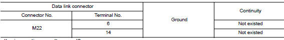
Is the inspection result normal? YES >> GO TO 4.
NO >> Check the harness and repair the root cause.
4.Check ecm and bcm termination circuit
- Remove the ecm and the bcm.
- Check the resistance between the ecm terminals.
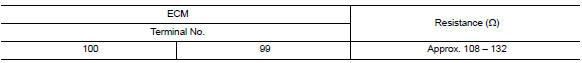
- Check the resistance between the bcm terminals.
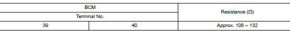
Is the measurement value within the specification? Yes >> go to 5.
No >> replace the ecm and/or the bcm.
5.Check symptom
Connect all the connectors. Check if the symptoms described in the “symptom (results from interview with customer)” are reproduced.
Inspection result
Reproduced>>go to 6.
Non-reproduced>>start the diagnosis again. Follow the trouble diagnosis procedure when past error is detected.
6.Check unit reproduction
Perform the reproduction test as per the following procedure for each unit.
- Turn the ignition switch off
- Disconnect the battery cable from the negative terminal.
- Disconnect one of the unit connectors of can communication system.
Note:
Ecm and bcm have a termination circuit. Check other units first.
- Connect the battery cable to the negative terminal. Check if the symptoms described in the “symptom (results from interview with customer)” are reproduced.
Note:
Although unit-related error symptoms occur, do not confuse them with other symptoms.
Inspection result
Reproduced>>connect the connector. Check other units as per the above procedure.
Non-reproduced>>replace the unit whose connector was disconnected.
 BCM branch line circuit
Diagnosis procedure
1.Check connector
Turn the ignition switch off.
Disconnect the battery cable from the negative terminal.
Check the terminals and connectors of the bcm for damage, bend and ...

Other materials:
A-bag branch line circuit
Diagnosis procedure
Warning:
Always observe the following items for preventing accidental
activation.
Before servicing, turn ignition switch off, disconnect battery
negative terminal, and wait 3 minutes
or more. (To discharge backup capacitor.)
Never use unspecified tester or other me ...
Main line between ipdm-e and dlc circuit
Diagnosis procedure
1.Check connector
Turn the ignition switch off.
Disconnect the battery cable from the negative terminal.
Check the following terminals and connectors for damage, bend and loose
connection (connector side
and harness side).
Harness connector e4
Harness connec ...
Symptom diagnosis
HEATER AND AIR CONDITIONING SYSTEM
CONTROL SYMPTOMS
Diagnosis Chart By Symptom
Note:
Perform the self-diagnoses with consult before performing the symptom
diagnosis. If dtc is detected, perform
the corresponding diagnosis.
INSUFFICIENT COOLING
Description
Symptom
Insufficient ...
