Nissan Sentra Service Manual: P0117, P0118 ECT Sensor
DTC Logic
DTC DETECTION LOGIC
| DTC No. | CONSULT screen terms (Trouble diagnosis content) | DTC detecting condition | Possible cause |
| P0117 | ECT SEN/CIRC (Engine coolant temperature sensor 1 circuit low) | An excessively low voltage from the engine coolant temperature sensor is sent to ECM. |
|
| P0118 | ECT SEN/CIRC (Engine coolant temperature sensor 1 circuit high) | An excessively high voltage from the engine coolant temperature sensor is sent to ECM. |
DTC CONFIRMATION PROCEDURE
1.PRECONDITIONING
If DTC Confirmation Procedure has been previously conducted, always perform the following procedure before conducting the next test.
- Turn ignition switch OFF and wait at least 10 seconds.
- Turn ignition switch ON.
- Turn ignition switch OFF and wait at least 10 seconds.
>> GO TO 2.
2.PERFORM DTC CONFIRMATION PROCEDURE
- Turn ignition switch ON and wait at least 5 seconds.
- Check DTC.
Is DTC detected? YES >> Proceed to EC-198, "Diagnosis Procedure".
NO >> INSPECTION END
Diagnosis Procedure
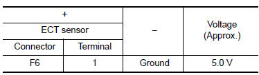
1.CHECK ENGINE COOLANT TEMPERATURE SENSOR POWER SUPPLY
- Turn ignition switch OFF.
- Disconnect engine coolant temperature (ECT) sensor harness connector.
- Turn ignition switch ON.
- Check the voltage between ECT sensor harness connector and ground.
Is the inspection result normal? YES >> GO TO 3.
NO >> GO TO 2.
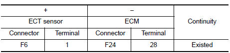
2.CHECK ENGINE COOLANT TEMPERATURE SENSOR POWER SUPPLY CIRCUIT
- Turn ignition switch OFF.
- Disconnect ECM harness connector.
- Check the continuity between ECT sensor harness connector and ECM harness connector.
- Also check harness for short to ground.
Is the inspection result normal? YES >> Perform the trouble diagnosis for power supply circuit.
NO >> Repair or replace error-detected parts.
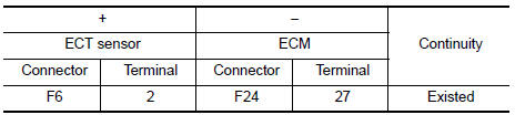
3.CHECK ENGINE COOLANT TEMPERATURE SENSOR GROUND CIRCUIT
- Turn ignition switch OFF.
- Disconnect ECM harness connector.
- Check the continuity between ECT sensor harness connector and ECM harness connector.
- Also check harness for short to ground to power.
Is the inspection result normal? YES >> GO TO 4.
NO >> Repair or replace error-detected parts.
4.CHECK ENGINE COOLANT TEMPERATURE SENSOR
Check the engine coolant temperature sensor. Refer to EC-199, "Component Inspection (ECT Sensor)".
Is the inspection result normal? YES >> Check intermittent incident. Refer to GI-39, "Intermittent Incident".
NO >> Replace engine coolant temperature sensor. Refer to CO-24, "Exploded View".
Component Inspection (ECT Sensor)
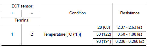
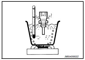
1.CHECK ENGINE COOLANT TEMPERATURE SENSOR
- Turn ignition switch OFF.
- Disconnect engine coolant temperature sensor harness connector.
- Remove engine coolant temperature sensor.
- Check resistance between engine coolant temperature sensor terminals by heating with hot water as shown in the figure.
Is the inspection result normal? YES >> INSPECTION END
NO >> Replace engine coolant temperature sensor. Refer to CO-24, "Exploded View".
 P0116 ECT Sensor
DTC Logic
DTC DETECTION LOGIC
DTC No.
CONSULT screen terms
(Trouble diagnosis content)
DTC detecting condition
Possible cause
P0116
ECT SEN/CIRC
(Engine coolant tem ...
 P0122, P0123 TP Sensor
DTC Logic
DTC DETECTION LOGIC
NOTE:
If DTC P0122 or P0123 is displayed with DTC P0643, first perform the
trouble diagnosis for DTC P0643.
Refer to EC-353, "DTC Logic".
DTC No ...
Other materials:
Towing recommended by NISSAN
(CVT) Continuously Variable Transmission
(M/T) Manual transmission
NISSAN recommends that your vehicle be towed
with the driving (front) wheels off the ground or
place the vehicle on a flat bed truck as illustrated.
(CVT) Continuously Variable Transmission
(M/T) Manual transm ...
Maintenance requirements
Your NISSAN has been designed to have minimum
maintenance requirements with long service
intervals to save you both time and money;
however, some day-to-day and regular maintenance
is essential to maintain your NISSAN’s
good mechanical condition as well as its emissions
and engine performanc ...
Diagnosis system (BCM)
Common item
Common item : consult function (bcm - common item)
Application item
Consult performs the following functions via can communication with bcm.
System application
Bcm can perform the following functions.
Intelligent key
Intelligent key : consult function (bcm - intelligent ke ...
