
Nissan Sentra Service Manual: Moonroof motor assembly
Exploded view
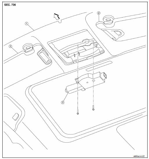
- Headlining
- Sun visor
- Moonroof motor assembly
 Front
Front
Removal and installation
REMOVAL
- Close the glass lid.
- Remove the map lamp. Refer to INL-52, "Removal and Installation".
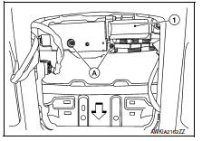
- Remove the moonroof motor bolts (A).
 Front
Front
- Disconnect the harness connector and remove the moonroof motor assembly (1).
CAUTION:
Do not run the removed moonroof motor assembly as a single unit.
INSTALLATION
- Move moonroof motor assembly laterally little by little so that the gear is completely engaged into the wire on the moonroof unit assembly, and the surfaces become parallel. Install the bolts and tighten.
CAUTION:
Before installing the motor, be sure to place the link and wire assembly in the symmetrical and fully closed position.
NOTE:
If necessary, insert a suitable tool into the drive key and rotate right or left slightly to assist in complete moonroof motor gear alignment
- Remainder of installation is in the reverse order of removal.
- Synchronize moonroof motor assembly with moonroof unit assembly.
 Glass lid
Exploded view
Glass lid
Roof panel
Front
Removal and installation
Removal
Caution:
After installing glass lid, check gap/height adjustments and
operation to make sure there is ...
 Moonroof unit assembly
Inspection
WIND DEFLECTOR
Open glass lid fully
Visually check for proper installation, damaged/deteriorated components,
or foreign objects within mechanism.
Correct as required for smoot ...
Other materials:
Ground
Ground distribution
Main harness
Engine room harness
Engine control harness
Body harness
...
Clutch master cylinder
Exploded View
Reservoir hose
Reservoir tank
Clutch master cylinder
Removal and Installation
REMOVAL
CAUTION:
Keep painted surface on the body or other parts free of clutch
fluid. If it spills, wipe up immediately
and wash the affected area with water.
Do not disassemble c ...
Driving on snow or ice
WARNING
Wet ice (32°F, 0°C and freezing rain),
very cold snow or ice can be slick and
very hard to drive on. The vehicle will
have much less traction or “grip� under
these conditions. Try to avoid driving on
wet ice until the road is salted or
sanded.
Wha ...
