
Nissan Sentra Service Manual: Hazard switch
Removal and Installation
REMOVAL
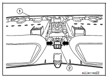
- Remove cluster lid C (1). Refer to IP-20, "Removal and Installation - Cluster Lid C".
- Release pawls at ( ) and remove hazard switch (2).
INSTALLATION
Installation is in the reverse order of removal.
 Combination switch
Exploded view
Combination switch
Combination switch harness connector
Front
NOTE:
Shown with the steering wheel removed for clarity only.
Removal and installation
REMOVAL
CAUTION:
...
 Optical sensor
Removal and installation
REMOVAL
Remove the defroster grille (LH) using a suitable tool.
Disconnect the harness connector from the optical sensor.
Release the pawls and remove the optical sen ...
Other materials:
AV branch line circuit
Diagnosis procedure
1.Check connector
Turn the ignition switch off
Disconnect the battery cable from the negative terminal.
Check the terminals and connectors of the av control unit for damage,
bend and loose connection (unit
side and connector side).
Is the inspection result normal ...
P0131 A/F Sensor 1
DTC Logic
DTC DETECTION LOGIC
To judge the malfunction, the diagnosis checks that the A/F signal computed
by ECM from the A/F sensor 1
signal is not inordinately low.
DTC No.
CONSULT screen terms
(Trouble diagnosis content)
DTC detecting condition
Possible cause
P01 ...
Power supply and ground circuit
WITH INTELLIGENT KEY SYSTEM
WITH INTELLIGENT KEY SYSTEM : Diagnosis Procedure
Regarding Wiring Diagram information, refer to BCS-51, "Wiring Diagram".
1.Check fuses and fusible link
Check that the following fuses and fusible link are not blown.
Is the fuse blown?
Yes >> r ...
