Nissan Sentra Service Manual: Front fog lamp circuit
Description
The ipdm e/r (intelligent power distribution module engine room) controls the front fog lamp relay based on inputs from the bcm over the can communication lines. When the front fog lamp relay is energized, power flows from the front fog lamp relay in the ipdm e/r to the front fog lamps.
Component Function Check
1.Check front fog lamp operation
 Without consult
- Activate ipdm e/r auto active test. Refer to exl-24, "diagnosis description" (with intelligent key system) or exl-28, "diagnosis description" (without intelligent key system).
- Check that the front fog lamp is turned ON.
 With consult
- Select EXTERNAL LAMP of IPDM E/R active test item.
- While operating the test items, check that the front fog lamp is turned on.
Fog : front fog lamp on
Off : front fog lamp off
Is the inspection result normal? YES >> Front fog lamp circuit is normal.
NO >> Refer to EXL-94, "Diagnosis Procedure".
Diagnosis Procedure
Regarding Wiring Diagram information, refer to EXL-53, "Wiring Diagram".
1.Check front fog lamp fuse
- Turn the ignition switch off.
- Check that the following fuse is not blown.

Is the fuse blown? YES >> Replace the fuse after repairing the affected circuit.
NO >> GO TO 2.
2.Check front fog lamp output voltage
 Consult
- Disconnect the front fog lamp harness connector in question.
- Turn the ignition switch on.
- Turn the front fog lamps on.
- Check the voltage between the front fog lamp harness connector and ground.
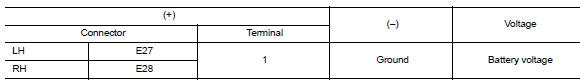
Is the inspection result normal? Yes >> go to 4.
NO >> GO TO 3.
3.Check front fog lamp open circuit
- Turn the ignition switch off.
- Disconnect IPDM E/R connector.
- Check continuity between the ipdm e/r harness connector and the front fog lamp harness connector.
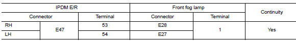
Is the inspection result normal? YES >> Replace IPDM E/R. Refer to PCS-30, "Removal and Installation" (with Intelligent Key system) or PCS-58, "Removal and Installation" (without Intelligent Key system).
NO >> Repair or replace the harness or connector.
4.Check front fog lamp ground circuit
- Turn the ignition switch off.
- Check continuity between the front fog lamp harness connector terminal 2 and ground.
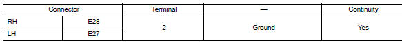
Is the inspection result normal? YES >> Inspect the fog lamp bulb.
NO >> Repair or replace the harness or connector.
 Daytime light relay circuit
Description
The bcm sends a daytime light request to the ipdm e/r via the can
communication lines. The power flows
through fuse 29 located in fuse block j/b to the daytime light relay coil. When
...
 Parking lamp circuit
Description
The ipdm e/r (intelligent power distribution module engine room) controls the
tail lamp relay based on inputs
from the bcm over the can communication lines. When the tail lamp relay i ...
Other materials:
P0448 EVAP Canister vent control valve
DTC Logic
DTC DETECTION LOGIC
DTC No.
CONSULT screen terms
(Trouble diagnosis content)
DTC detecting condition
Possible cause
P0448
VENT CONTROL VALVE
(Evaporative emission system
vent control circuit shorted)
EVAP canister vent control valve remains
clos ...
Body component parts
Moonroof panel assembly
Roof panel assembly
Front roof rail
Roof rail
Rear roof rail
Moonroof frame assembly
Hood assembly
Front fender (RH, LH)
Outer front door panel (RH, LH)
Outer rear door panel (RH, LH)
Front door assembly (RH, LH)
Rear door assembly (RH, LH)
Fron ...
Symptom diagnosis
Multi av system
Symptom table
Related to audio
Related to hands-free phone
Before performing diagnosis, confirm that the cellular phone being used
by the customer is compatible with
the vehicle.
It is possible that a malfunction is occurring due to a version change
of th ...
