Nissan Sentra Service Manual: Daytime light relay circuit
Description
The bcm sends a daytime light request to the ipdm e/r via the can communication lines. The power flows through fuse 29 located in fuse block j/b to the daytime light relay coil. When the ipdm e/r operates the daytime light relay, power is sent to the daytime lamps.
Diagnosis procedure
Regarding Wiring Diagram information, refer to EXL-38, "Wiring Diagram".
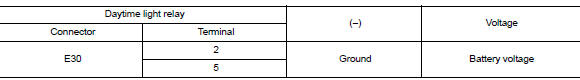
1.Check daytime light relay voltage supply
- Turn the ignition switch off.
- Remove the daytime light relay.
- Check the voltage between the daytime light relay harness connector and ground.
Is the inspection result normal? Yes >> go to 3.
No >> go to 2.
2.Check daytime light relay fuse
Check that the following fuses are not blown.

Is the fuse blown? Yes >> replace the blown fuse after repairing the affected circuit.
No >> repair or replace the harness or connector.
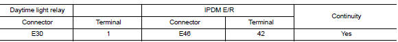
3.Check daytime light relay control circuit
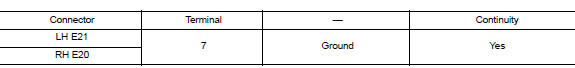
- Check continuity between the IPDM E/R harness connector and the daytime light relay harness connector.
- Check continuity between the daytime light relay harness connector and ground.

Is the inspection result normal? Yes >> go to 4.
No >> repair or replace the harness or connector.
4.Check daytime light relay
Check the daytime light relay. Refer to exl-93, "component inspection".
Is the inspection result normal? YES >> GO TO 5.
NO >> Replace relay.
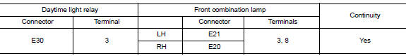
5.Check daytime light circuit (open or short to ground)
- Check continuity between the daytime light relay harness connector and the front combination lamp harness connector.
- Check continuity between the daytime light relay harness connector and ground.
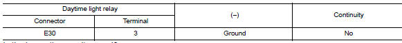
Is the inspection result normal? Yes >> go to 6.
No >> repair or replace the harness or connector.
6.Check daytime light ground circuit for open
- Disconnect front combination lamp connector in question.
- Check continuity between the front combination lamp connector and ground.
Is the inspection result normal? Yes >> inspect daytime light bulb.
No >> repair or replace the harness or connector.
Component inspection
1. Check daytime light relay
- Turn ignition switch off.
- Remove daytime light relay.
- Check the continuity between daytime light relay terminals 3 and 5 when voltage is supplied between terminals 1 and 2.
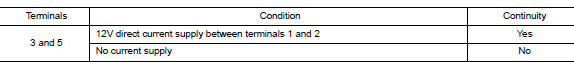
Is the inspection result normal? Yes >> inspection end.
No >> replace daytime light relay.
 Headlamp (lo) circuit
Description
The ipdm e/r (intelligent power distribution module engine room) controls the
headlamp low relay based on
inputs from the bcm over the can communication lines. When the headlamp low
...
 Front fog lamp circuit
Description
The ipdm e/r (intelligent power distribution module engine room) controls the
front fog lamp relay based on
inputs from the bcm over the can communication lines. When the front fog lam ...
Other materials:
Removal and installation
Hood
Hood assembly
Hood assembly : exploded view
Hood hinge (LH/RH)
Hood assembly
Hood bumper rubber
Hood seal
Hood insulator
Hood support rod
Hood support rod clamp
Clip
Hood assembly : removal and installation
CAUTION:
Use two people when removing or installin ...
Wiring diagram
Sport mode system
Wiring diagram
...
Removal and installation
Av control unit
Exploded view
Av control unit
Av control unit bracket (lh)
Av control unit bracket (rh)
Removal and installation
Removal
Caution:
Remove battery terminal and av control unit after a lapse of 30
seconds or more after turning the
ignition switch off.
Befor ...
