Nissan Sentra Service Manual: Evaporative emission system
EVAPORATIVE EMISSION SYSTEM : System Description
SYSTEM DIAGRAM
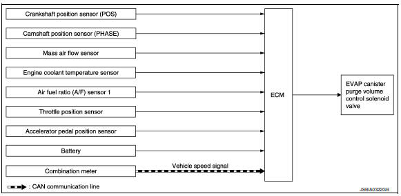
INPUT/OUTPUT SIGNAL CHART
| Sensor | Input signal to ECM | ECM function | Actuator | |
| Crankshaft position sensor (POS) | Engine speed* | EVAP canister purge flow control | EVAP canister purge volume control solenoid valve | |
| Camshaft position sensor (PHASE) | ||||
| Mass air flow sensor | Amount of intake air | |||
| Engine coolant temperature sensor | Engine coolant temperature | |||
| Air fuel ratio (A/F) sensor 1 | Density of oxygen in exhaust gas (Mixture ratio feedback signal) | |||
| Throttle position sensor | Throttle position | |||
| Accelerator pedal position sensor | Accelerator pedal position | |||
| Battery | Battery voltage* | |||
| Combination meter | CAN communication | Vehicle speed signal | ||
*: ECM determines the start signal status by the signals of engine speed and battery voltage.
SYSTEM DESCRIPTION
The evaporative emission system is used to reduce hydrocarbons emitted into the atmosphere from the fuel system. This reduction of hydrocarbons is accomplished by activated charcoals in the EVAP canister.
The fuel vapor in the sealed fuel tank is led into the EVAP canister which contains activated carbon and the vapor is stored there when the engine is not operating or when refueling to the fuel tank.
The vapor in the EVAP canister is purged by the air through the purge line to the intake manifold when the engine is operating. EVAP canister purge volume control solenoid valve is controlled by ECM. When the engine operates, the flow rate of vapor controlled by EVAP canister purge volume control solenoid valve is proportionally regulated as the air flow increases.
EVAP canister purge volume control solenoid valve also shuts off the vapor purge line during decelerating and idling.
 Starter motor drive control
STARTER MOTOR DRIVE CONTROL : System Description
SYSTEN DIAGRAM
*1: CVT models
*2: M/T models
INPUT/OUTPUT SIGNAL CHART
Sensor
Input signal to ECM
ECM function
Actuator
...
 Automatic speed control device (ASCD)
AUTOMATIC SPEED CONTROL DEVICE (ASCD) : System Description
SYSTEM DIAGRAM
BASIC ASCD SYSTEM
Refer to Owner's Manual for ASCD operating instructions.
Automatic Speed Control Device (ASCD) all ...
Other materials:
Automatic anti-glare rearview mirror (if so equipped)
The inside mirror is designed so that it automatically
dims according to the intensity of the headlights
of the vehicle following you. The automatic
anti-glare feature is activated when the ignition
switch is in the ON position.
NOTE:
Do not hang any objects over the sensors
1 or apply gl ...
Precaution for Supplemental Restraint System
(SRS) "AIR BAG" and "SEAT BELT PRE-TENSIONER"
The Supplemental Restraint System such as ą▓ąéčÜAIR BAGą▓ąéč£ and ą▓ąéčÜSEAT BELT PRE-TENSIONERą▓ąéč£,
used along
with a front seat belt, helps to reduce the risk or severity of injury to the
driver and front passenger for certain
types of collision. Information necessary to service the system ...
Storage pouch
A storage pouch is located on the front of the
driverŌĆÖs and passengerŌĆÖs seats.
WARNING
Do not store angular, sharp, heavy objects
or objects that cannot fully fit inside
the pouch because they might increase
the likelihood of an injury in a
crash.
To ensure ...
