Nissan Sentra Service Manual: Ecu diagnosis information
Bcm
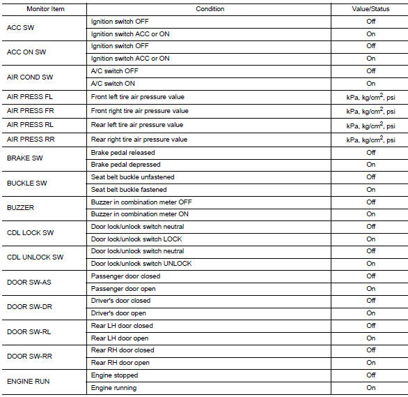
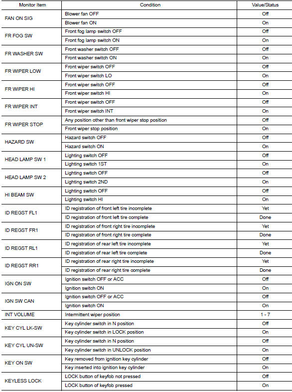
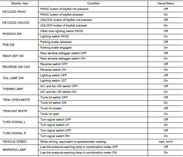
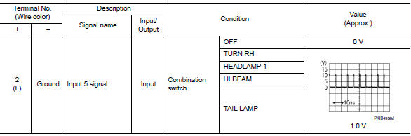
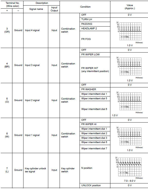
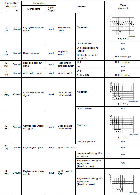
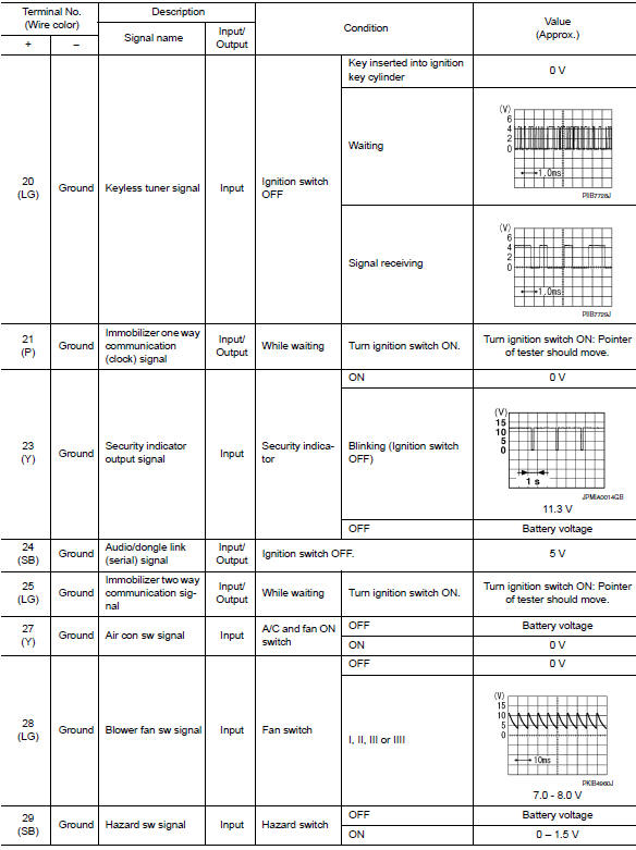
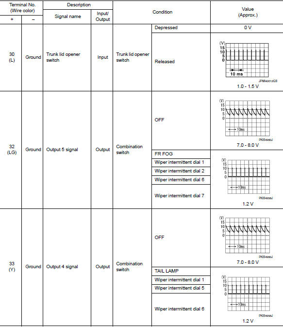
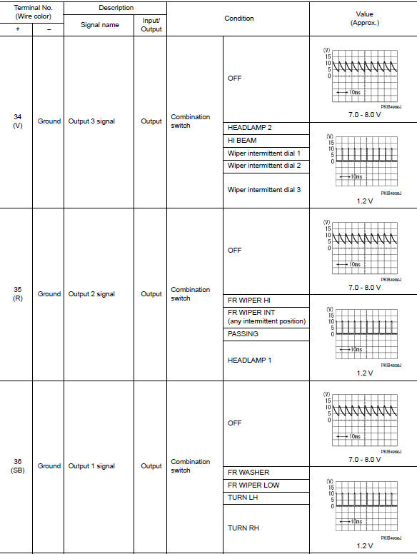
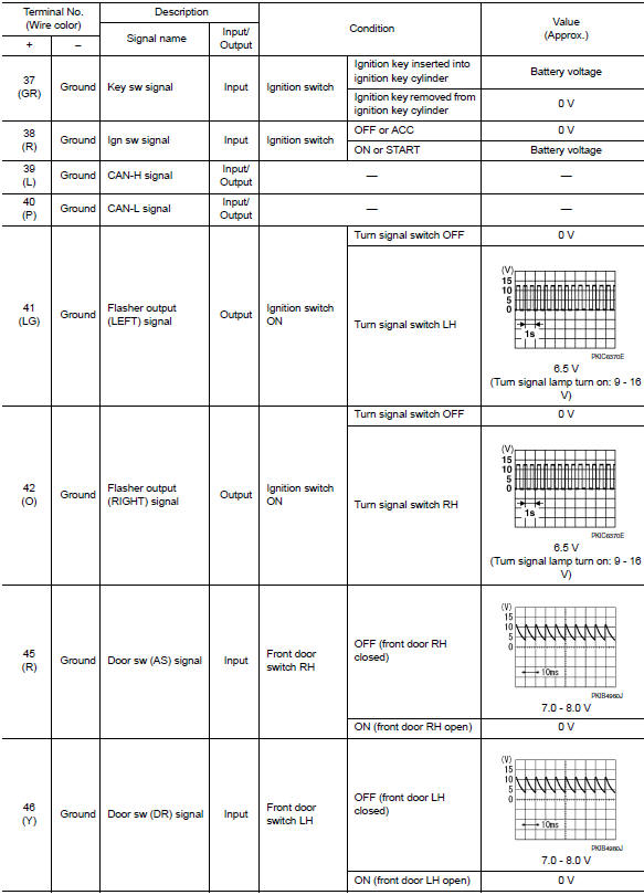
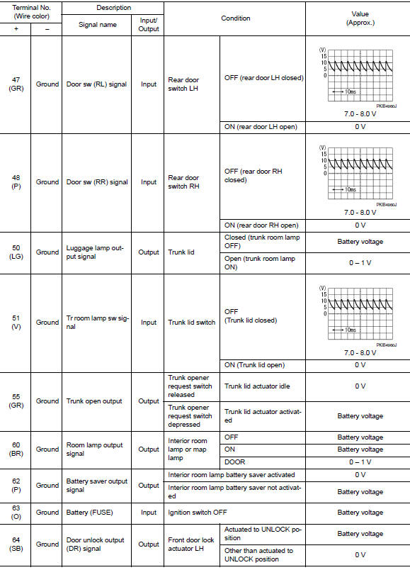
Reference value
NOTE:
The Signal Tech II Tool (J-50190) can be used to perform the following functions. Refer to the Signal Tech II User Guide for additional information.
- Activate and display TPMS transmitter IDs
- Display tire pressure reported by the TPMS transmitter
- Read TPMS DTCs
- Register TPMS transmitter IDs
- Test remote keyless entry keyfob relative signal strength
VALUES ON THE DIAGNOSIS TOOL
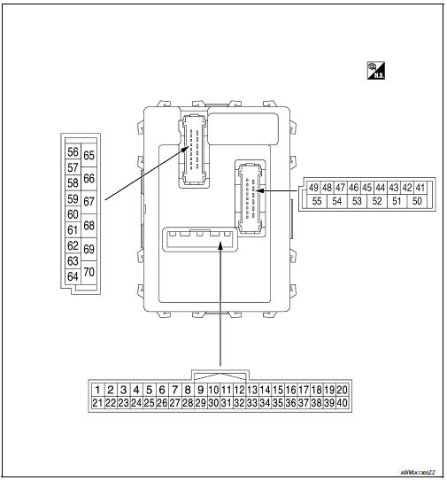
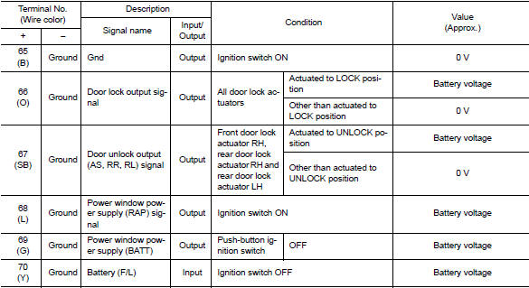
Terminal layout
Physical values
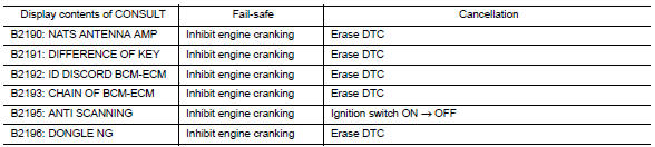
Fail-safe
Fail-safe control by dtc
Bcm performs fail-safe control when any dtc are detected.
Fail-safe control of combination switch reading function caused by low power supply voltage
If voltage of battery power supply lower, BCM maintains combination switch reading to the status when input voltage is less than approximately 9 V.
Note:
When voltage of battery power supply is approximately 9 v or more, combination switch reading function returns to normal operation.
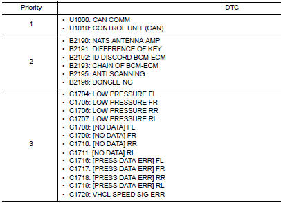
Dtc inspection priority chart
If some dtcs are displayed at the same time, perform inspections one by one based on the following priority chart.
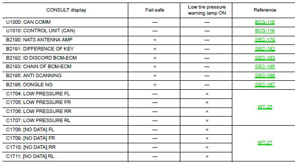
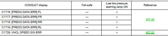
Dtc index
Note:
Details of time display
- Crnt: displays when there is a malfunction now or after returning to the normal condition until turning ignition switch off ƒ¸ on again.
- 1 - 39: Displayed if any previous malfunction is present when current condition is normal. It increases like 1 → 2 → 3...38 → 39 after returning to the normal condition whenever ignition switch OFF → ON. The counter remains at 39 even if the number of cycles exceeds it. It is counted from 1 again when turning ignition switch OFF → ON after returning to the normal condition if the malfunction is detected again.
 Diagnosis system (bcm)
Common item
Common item : consult function (bcm - common item)
APPLICATION ITEM
CONSULT performs the following functions via CAN communication with BCM.
Direct Diagnostic Mode
Descriptio ...
 Wiring diagram
BCM
Wiring diagram
...
Other materials:
Starting system (without intelligent key)
Wiring Diagram
...
Fuel gauge
NOTE:
The ignition switch must be placed in the
ON position for the gauge to give a reading.
The gauge indicates the approximate fuel level
in the tank.
The gauge may move slightly during braking,
turning, acceleration, or going up or down hills.
The low fuel warning light comes on when ...
Shift position indicator circuit
Component Parts Function Inspection
1.CHECK SHIFT POSITION INDICATOR
Start the engine.
Shift selector lever.
Check that the selector lever position and the shift position indicator
on the combination meter are identical.
Is the inspection result normal?
YES >> INSPECTION END
N ...
