Nissan Sentra Service Manual: ECU diagnosis information
Diagnosis sensor unit
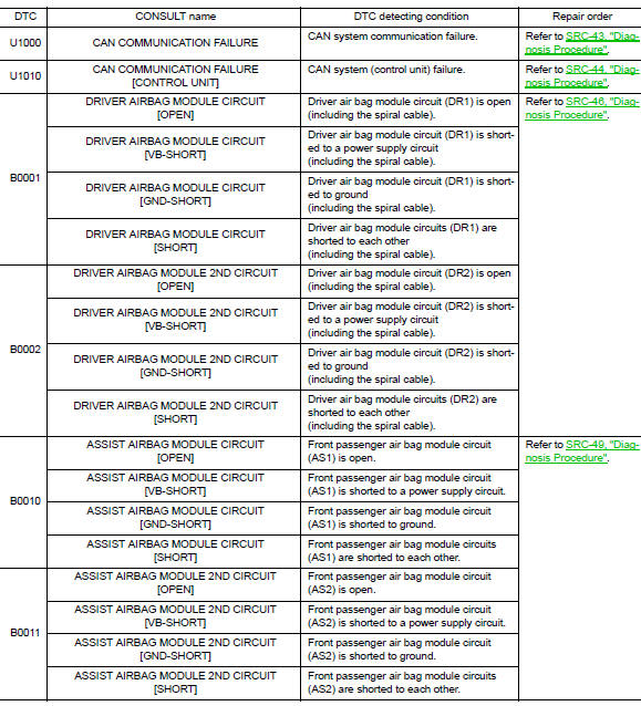
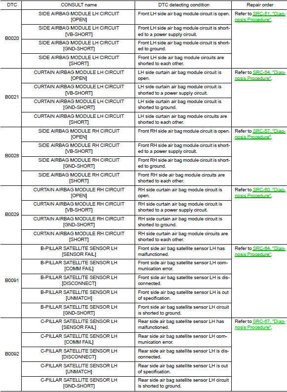
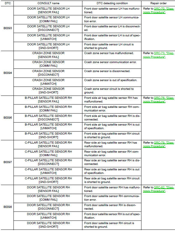
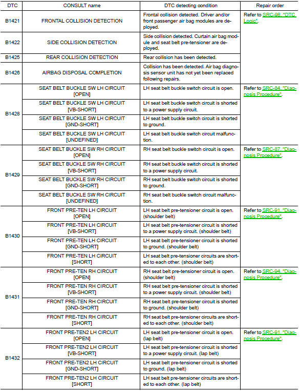
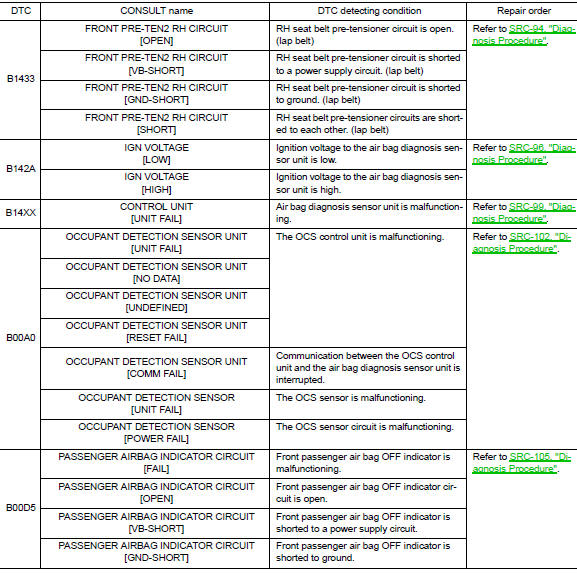
DTC Index
DIAGNOSTIC CODE CHART
NOTE:
Follow the procedures in numerical order when repairing malfunctioning parts. Confirm whether malfunction is eliminated using air bag warning lamp or CONSULT each time repair is finished. If malfunction is still observed, proceed to the next step. When malfunction is eliminated, further repair work is not required.
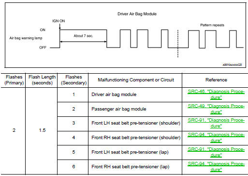
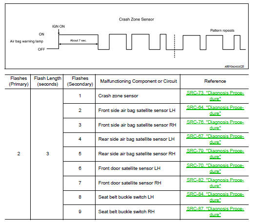
Flash Code Index
WARNING LAMP FLASH CODE CHART
How to read flash codes
- Put the vehicle in Diagnosis Mode. Refer to SRC-17, "Trouble Diagnosis without CONSULT".
- All codes are proceded by a seven second ”holding” flash.
- Identify how many primary flashes are displayed as well as the length of each primary flash.
- Refer to the tables and examples below to determine which SRS subsystem the code belongs to.
- Count the short secondary flashes that follow the primary flashes.
- Match the correct flashing pattern to the malfunctioning component and perform the Diagnosis Procedure.
Refer to the illustrations below for an example of each flashing pattern.
Front subsystem
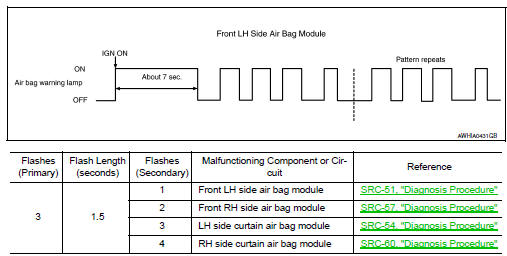
Side subsystem
Air bag subsystem
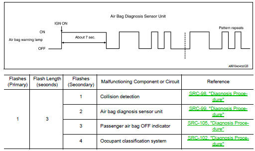
Sensor subsystem
 Diagnosis system (AIR BAG)
Description
CAUTION:
Never use electrical test equipment on any circuit related to the
SRS unless instructed in this Service
Manual. SRS wiring harnesses can be identified by yellow and/or o ...
 Wiring diagram
SRS AIR BAG SYSTEM
Wiring Diagram
...
Other materials:
Eps branch line circuit
Diagnosis procedure
1.Check connector
Turn the ignition switch off.
Disconnect the battery cable from the negative terminal.
Check the terminals and connectors of the eps control unit for damage,
bend and loose connection (unit
side and connector side).
Is the inspection result norm ...
Compressor
Exploded view
With air conditioning
Compressor
Front
Without air conditioning
A/c idler pulley
A/c idler pulley bracket
Compressor
Compressor : removal and installation
REMOVAL
Discharge the refrigerant. Refer to ha-23, "recycle refrigerant".
Remove the fr ...
Instrument panel assembly
Exploded View
Instrument panel assembly
Ambient sensor
Defroster grille (RH)
Defroster grille (LH)
Sunload sensor (if equipped)
Side defroster grille (LH)
Instrument side finisher (LH)
Side ventilator grille (LH)
Steering column upper cover
Combination switch
Steering col ...
