Nissan Sentra Service Manual: Compressor
Exploded view
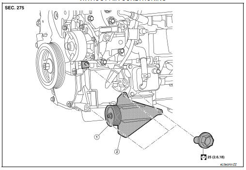
With air conditioning
- Compressor
 Front
Front
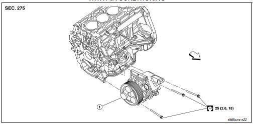
Without air conditioning
- A/c idler pulley
- A/c idler pulley bracket
Compressor
Compressor : removal and installation
REMOVAL
- Discharge the refrigerant. Refer to ha-23, "recycle refrigerant".
- Remove the front under cover. Refer to ext-31, "engine under cover : removal and installation".
- Partially remove the front fender protector (rh). Refer to ext-28, "fender protector : removal and installation - front fender protector".
- Remove the drive belt from the compressor. Refer to EM-15, "Removal and Installation".
Note:
Complete removal of the drive belt is not necessary.
- Remove the bolt that retains the high-pressure flexible hose to the compressor, then disconnect the highpressure flexible hose from the compressor.
Caution:
Cap or wrap the joint of the a/c pipes with suitable material such as vinyl tape to avoid the entry of air.
- Remove the bolt that retains the low-pressure flexible hose to the compressor, then disconnect the lowpressure flexible hose from the compressor.
- Disconnect the harness connector from the compressor.
- Remove the compressor bolts and the compressor.
Installation
Installation is in the reverse order of removal.
Caution:
- Do not reuse the o-rings.
- Apply a/c compressor oil to the new o-rings for installation.
- After charging the a/c refrigerant, check for leaks. Refer to ha-21, "leak test".
- Tighten the compressor bolts to the specified torque. Refer to HA-30, "Exploded View".
Magnet clutch
Magnet clutch : removal and installation
Removal
- Remove the compressor. Refer to ha-31, "compressor : removal and installation".
- Remove the center bolt by holding the clutch disc steady using the clutch disc holding tool.
Tool number : (j-44614)
- Remove the clutch disc and shim(s).
Caution:
Retain shim(s) for installation.
- Remove the snap ring using external snap ring pliers.
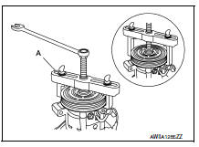
- Remove the pulley assembly using suitable tool (a).
Caution:
To prevent deformation of the pulley groove, the puller claws should be hooked under (not into) the pulley groove.
- Remove the magnet coil snap ring (a) using a suitable tool.
Then remove the magnet coil (1) from compressor shaft.
Inspection after removal
Clutch disc
If the contact surface shows signs of damage due to excessive heat, replace clutch disc and pulley.
Pulley
Check the appearance of the pulley assembly. If the contact surface of the pulley shows signs of excessive grooving, replace the clutch disc and pulley. The contact surfaces of the pulley assembly should be cleaned with a suitable solvent before installation.
Magnet Coil
Check the magnet coil for a loose connection or cracked insulation.
INSTALLATION
- Install the magnet coil.
CAUTION:
Be sure to align the magnet coil pin with the hole in the compressor front head.
- Install the magnet coil (1) on the compressor shaft with the snap ring (A) using suitable tool.
- Install the pulley assembly using the drive plate installer and a wrench, then install the snap ring using snap ring pliers.
Tool number : — (J-38873-A)
- Install the clutch disc on the drive shaft, together with the original shim(s). Press the clutch disc down using the drive plate installer.
- Install the center bolt using the clutch disc holding tool.
- After installation, check that the pulley rotates smoothly.
- Install the compressor. Refer to HA-31, "COMPRESSOR : Removal and Installation".
INSPECTION OF CLUTCH DISC TO PULLEY CLEARANCE
- Check the clearance around the entire periphery of the clutch disc.
Clutch disc to pulley clearance : 0.3 - 0.6 mm (0.01 - 0.02 in)
- If specified clearance is not obtained, replace compressor clutch.
BREAK-IN OPERATION
When replacing compressor clutch assembly, always conduct the break-in operation. This is done by engaging and disengaging the clutch about 30 times. Break-in operation raises the level of transmitted torque.

 Cooler pipe and hose
Exploded view
High-pressure service port
High-pressure pipe
Expansion valve
Low-pressure service port
Low-pressure flexible hose
Compressor
Refrigerant pressure sensor
Condenser ...
Other materials:
Clutch fluid
Inspection
FLUID LEAKAGE
Check clutch line for cracks, deterioration or other damage. Replace any
damaged parts.
Check for fluid leakage by fully depressing clutch pedal while engine is
running.
CAUTION:
If leakage occurs around connections, reinstall the lines or replace
damaged ...
Bluetooth® Hands-Free Phone System voice commands
To access the Bluetooth® Hands-Free Phone
System voice commands:
Press the button.
Say “Call” and then a name in the vehicle
phonebook to call that entry. Otherwise, say
“Phone” to access various phone commands.
If the Bluetooth® has been set to “Off”, the
system announ ...
Fuel gauge
NOTE:
The ignition switch must be placed in the
ON position for the gauge to give a reading.
The gauge indicates the approximate fuel level
in the tank.
The gauge may move slightly during braking,
turning, acceleration, or going up or down hills.
The low fuel warning light comes on when ...
