
Nissan Sentra Service Manual: Door outside molding
Exploded view
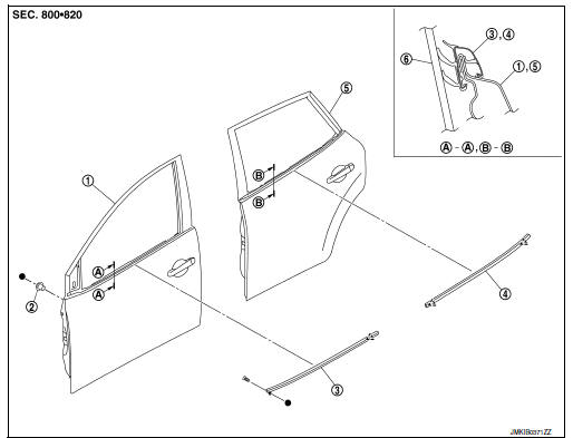
- Front door assembly
- Grommet
- Front door outside molding
- Rear door outside molding
- Rear door assembly
- Door glass
 Clip
Clip
Front door outside molding
FRONT DOOR OUTSIDE MOLDING : Removal and Installation
REMOVAL
- Remove front door mirror. Refer to MIR-18, "DOOR MIRROR ASSEMBLY : Removal and Installation".
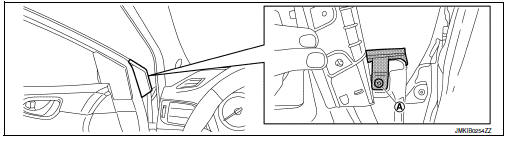
- Remove front door outside molding screw (A).
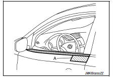
- Apply protective tape (A) to protect the component from damage.
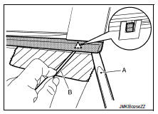
- Release rear end of front door outside molding clip using suitable tools (A,B).
 Clip
Clip
- Rotate and lift as shown to remove the front door outside molding.
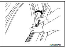
INSTALLATION
Installation is in the reverse order of removal.
Rear door outside molding
Rear door outside molding : removal and installation
REMOVAL
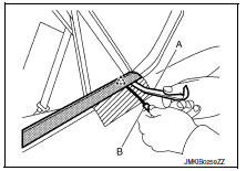
- Apply protective tape (A) to protect the component from damage.
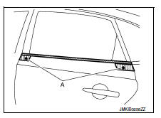
- Release clip of rear door outside molding front and rear end, using suitable tools (A, B).
 : Clip
CAUTION:
Use care when lifting rear door outside molding to prevent damage.
- Rotate and lift as shown to remove the rear door outside molding.
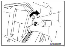
INSTALLATION
Installation is in the reverse order of removal.
 Door sash tape
Exploded view
Front door sash upper tape
Front door assembly
Rear door assembly
Front door sash rear tape
Rear door sash front tape
Rear door sash rear tape
Rear door sash upper ta ...
 Door parting seal
Exploded View
Rear door panel
Rear door parting seal
Front door parting seal
Front door panel
Pawl
Front
Removal and Installation
Release parting seal pawls, then remove parti ...
Other materials:
P2122, P2123 APP Sensor
DTC Logic
DTC DETECTION LOGIC
NOTE:
If DTC P2122 or P2123 is displayed with DTC P0643, first perform the
trouble diagnosis for DTC P0643.
Refer to EC-353, "DTC Logic".
DTC No.
CONSULT screen terms
(Trouble diagnosis content)
DTC detecting condition
Possible caus ...
iPod®* player operation with Navigation System (if so equipped)
Connecting iPod®
WARNINGDo not connect, disconnect or operate the
USB device while driving. Doing so can be
a distraction. If distracted you could lose
control of your vehicle and cause an accident
or serious injury.
CAUTION
Do not force the USB device into the
U ...
Environmental factors influence the rate of corrosion
Moisture
Accumulation of sand, dirt and water on the vehicle
body underside can accelerate corrosion.
Wet floor coverings will not dry completely inside
the vehicle and should be removed for drying to
avoid floor panel corrosion.
Relative humidity
Corrosion will be accelerated in areas of h ...
