Nissan Sentra Service Manual: Wheel sensor
Front wheel sensor
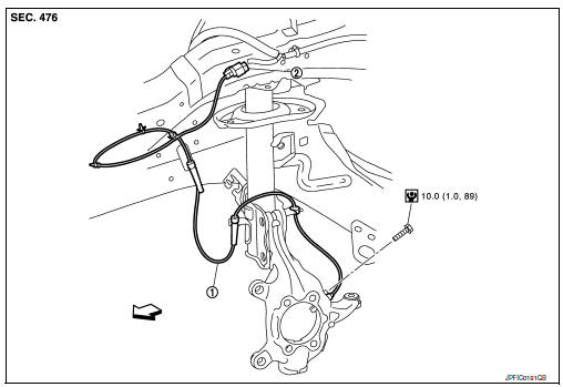
FRONT WHEEL SENSOR : Exploded View
-
Front wheel sensor
-
Front wheel sensor harness connector
 Front
Front
FRONT WHEEL SENSOR : Removal and Installation
CAUTION:
-
Be careful not to damage wheel sensor edge and sensor rotor teeth.
-
When removing the front or rear wheel hub, first remove the wheel sensor from the wheel hub. Failure to do so may result in damage to the wheel sensor wires, making the sensor inoperative.
-
Pull out the wheel sensor, being careful to turn it as little as possible. Do not pull on the wheel sensor harness.
-
Before installation, check if foreign objects such as iron fragments are adhered to the pick-up part of the sensor or to the inside of the hole in the wheel hub for the wheel sensor, or if a foreign object is caught in the surface of the mating surface for the sensor rotor. Clean as necessary and then install the wheel sensor.
REMOVAL
-
Remove the front wheels and tires using power tool. Refer to WT-47, "Adjustment".
-
Remove the fender protector (front). Refer to EXT-28, "FENDER PROTECTOR : Removal and Installation - Front Fender Protector".
-
Disconnect front wheel sensor harness connector.
-
Disconnect front wheel sensor harness from brackets.
-
Remove front wheel sensor bolt.
-
Remove front wheel sensor.
INSTALLATION
Installation is in the reverse order of removal.
CAUTION:
-
During installation, make sure there is no foreign material such as iron chips on and in the mounting hole of the wheel sensor. Make sure no foreign material has been caught in the sensor rotor. Remove and foreign material and clean the mount.
-
Do not twist front wheel sensor harness when installing front wheel sensor. Check that grommet (2) is fully inserted to bracket (1). Check that front wheel sensor harness is not twisted after installation.
Rear wheel sensor
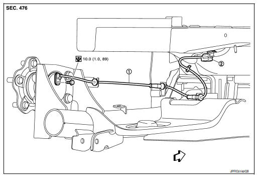
REAR WHEEL SENSOR : Exploded View
-
Rear wheel sensor
-
Rear wheel sensor harness connector
 Front
Front
REAR WHEEL SENSOR : Removal and Installation
CAUTION:
-
Be careful not to damage wheel sensor edge and sensor rotor teeth.
-
When removing the front or rear wheel hub, first remove the wheel sensor from the wheel hub. Failure to do so may result in damage to the wheel sensor wires, making the sensor inoperative.
-
Pull out the wheel sensor, being careful to turn it as little as possible. Do not pull on the wheel sensor harness.
-
Before installation, check if foreign objects such as iron fragments are adhered to the pick-up part of the sensor or to the inside of the hole in the wheel hub for the wheel sensor, or if a foreign object is caught in the surface of the mating surface for the sensor rotor. Clean as necessary and then install the wheel sensor.
REMOVAL
-
Remove rear wheel sensor harness connector.
-
Remove rear wheel sensor bolt.
-
Remove rear wheel sensor harness from the brackets.
INSTALLATION
Installation is in the reverse order of removal.
CAUTION:
-
During installation, make sure there is no foreign material such as iron chips on and in the mounting hole of the wheel sensor. Make sure no foreign material has been caught in the sensor rotor. Remove and foreign material and clean the mount.
-
Do not twist front wheel sensor harness when installing front wheel sensor. Check that grommet (2) is fully inserted to bracket (1). Check that front wheel sensor harness is not twisted after installation.

 Sensor rotor
Front sensor rotor
FRONT SENSOR ROTOR : Removal and Installation
The front wheel sensor rotor is an integral part of the wheel
hub and bearing assembly and cannot be disassembled.
Refer to FAX- ...
Other materials:
Rear seat
Exploded View
Rear seatback assembly (RH)
Seatback striker
Seatback latch release knob
Seatback latch assembly
Seatback silencer (RH)
Rear seatback frame (RH)
Seatback latch release knob finisher
Rear seat bolster trim (RH)
Rear seat bolster pad (RH)
Rear seat bolster (RH)
...
Wiring diagram
Intelligent key system/engine start function
Wiring diagram
Nissan vehicle immobilizer systemnats
Wiring Diagram
Vehicle security system
Wiring diagram
...
Ignition signal
Component Function Check
1.INSPECTION START
Turn ignition switch OFF.
Start engine.
Does the engine start?
YES >> GO TO 2.
NO >> Proceed to EC-456, "Diagnosis Procedure".
2.IGNITION SIGNAL FUNCTION
With CONSULT
Perform “POWER BALANCE” in “ACT ...
