
Nissan Sentra Service Manual: Diagnosis system (ipdm e/r) (with intelligent key system)
Diagnosis Description
AUTO ACTIVE TEST
Description
In auto active test, the IPDM E/R sends a drive signal to the following systems to check their operation.
- Front wiper (LO, HI)
- Parking lamp
- License plate lamp
- Tail lamp
- Front fog lamp (if equipped)
- Headlamp (LO, HI)
- A/C compressor (magnet clutch)
- Cooling fan
Operation Procedure
NOTE:
Never perform auto active test in the following conditions.
- Passenger door is open
- CONSULT is connected
- Close the hood and lift the wiper arms from the windshield. (Prevent windshield damage due to wiper operation)
NOTE:
When auto active test is performed with hood opened, sprinkle water on windshield beforehand
- Turn the ignition switch OFF
- Turn the ignition switch ON, and within 20 seconds, press the driver door switch 10 times. Then turn the ignition switch OFF
- Turn the ignition switch ON within 10 seconds. After that the horn sounds once and the auto active test starts.
- After a series of the following operations is repeated 3 times, auto active test is completed.
NOTE:
- When auto active test has to be cancelled halfway through test, turn the ignition switch OFF.
- When auto active test is not activated, door switch may be the cause. Check door switch. Refer to DLK-103, "Component Inspection".
Inspection in Auto Active Test
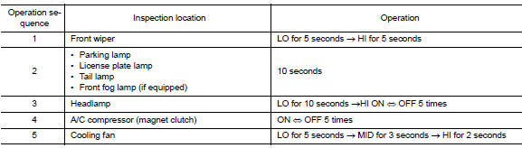
When auto active test is actuated, the following operation sequence is repeated 3 times.
Concept of Auto Active Test
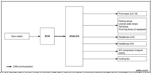
- IPDM E/R starts the auto active test with the door switch signals
transmitted by BCM via CAN communication.
Therefore, the CAN communication line between IPDM E/R and BCM is considered normal if the auto active test starts successfully
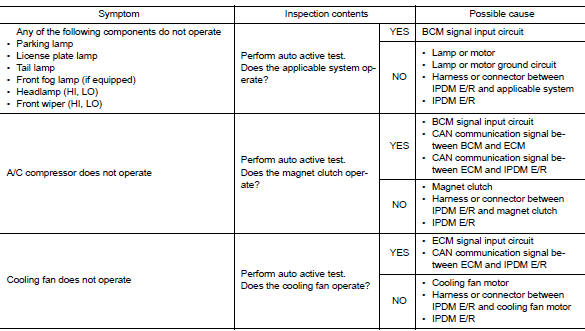
- The auto active test facilitates troubleshooting if any systems controlled by IPDM E/R cannot be operated.
Diagnosis Chart in Auto Active Test
CONSULT Function (IPDM E/R)
APPLICATION ITEM
CONSULT performs the following functions via CAN communication with IPDM E/R.
| Direct Diagnostic Mode | Description |
| Ecu Identification | The IPDM E/R part number is displayed. |
| Self Diagnostic Result | The IPDM E/R self diagnostic results are displayed. |
| Data Monitor | The IPDM E/R input/output data is displayed in real time. |
| Active Test | The IPDM E/R activates outputs to test components. |
| CAN Diag Support Mntr | The result of transmit/receive diagnosis of CAN communication is displayed. |
ECU IDENTIFICATION
The IPDM E/R part number is displayed.
SELF DIAGNOSTIC RESULT
Refer to PCS-20, "DTC Index".
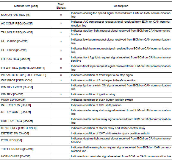
DATA MONITOR
ACTIVE TEST


CAN DIAG SUPPORT MNTR
Refer to LAN-13, "CAN Diagnostic Support Monitor".
 Diagnosis system (bcm) (without intelligent key system)
Common item
COMMON ITEM : CONSULT Function (BCM - COMMON ITEM)
APPLICATION ITEM
CONSULT performs the following functions via CAN communication with BCM.
SYSTEM APPLICATION
BCM can perform the ...
 Diagnosis system (ipdm e/r) (without intelligent key system)
Diagnosis Description
AUTO ACTIVE TEST
Description
In auto active test, the IPDM E/R sends a drive signal to the following
systems to check their operation.
Front wiper (LO, HI)
Parking lam ...
Other materials:
Moonroof switch
Removal and installation
REMOVAL
Remove the map lamp. Refer to INL-52, "Removal and Installation".
Release the pawls and remove the moonroof switch finisher (1).
: Pawl
Release the pawls and remove the moonroof switch (2).
: Pawl
INSTALLATION
Installation is in the ...
Sun visors
To block glare from the front, swing down the
sun visor.
To block glare from the side, remove the sun
visor from the center mount and swing the
visor to the side.
Slide the extension sun visor in or out as
needed.
CAUTION
Do not store the sun visor before returning
the exte ...
Power generation voltage variable control system
System Diagram
System Description
Power generation variable voltage control system has been adopted. By varying
the voltage to the generator,
engine load due to power generation of the generator is reduced and fuel
consumption is decreased.
NOTE:
When any malfunction is detected in the ...
