Nissan Sentra Service Manual: Diagnosis description : counter system
RELATIONSHIP BETWEEN MIL, 1ST TRIP DTC, DTC, AND DETECTABLE ITEMS
- When a malfunction is detected for the first time, the 1st trip DTC and the 1st trip freeze frame data are stored in the ECM memory.
- When the same malfunction is detected in two consecutive trips, the DTC and the freeze frame data are stored in the ECM memory, and the MIL will come on.
- The MIL will turn OFF after the vehicle is driven 3 times (driving pattern B) with no malfunction. The drive is counted only when the recorded driving pattern is met (as stored in the ECM). If another malfunction occurs while counting, the counter will reset.
- The DTC and the freeze frame data will be stored until the vehicle is driven 40 times (driving pattern A) without the same malfunction recurring (except for Misfire and Fuel Injection System). For Misfire and Fuel Injection System, the DTC and freeze frame data will be stored until the vehicle is driven 80 times (driving pattern C) without the same malfunction recurring. The “TIME” in “SELF-DIAGNOSTIC RESULTS” mode of CONSULT will count the number of times the vehicle is driven.
- The 1st trip DTC is not displayed when the self-diagnosis results in OK for the 2nd trip.
Counter system chart
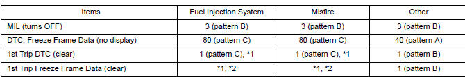
For details about patterns B and C under “Fuel Injection System” and “Misfire”, see “EXPLANATION FOR DRIVING PATTERNS FOR “MISFIRE <EXHAUST QUALITY DETERIORATION>”, “FUEL INJECTION SYSTEM”.
For details about patterns A and B under Other, see “EXPLANATION FOR DRIVING PATTERNS FOR “MISFIRE <EXHAUST QUALITY DETERIORATION>”, “FUEL INJECTION SYSTEM”.
- *1: Clear timing is at the moment OK is detected.
- *2: Clear timing is when the same malfunction is detected in the 2nd trip.
Relationship Between MIL, DTC, 1st Trip DTC and Driving Patterns for “Misfire <Exhaust Quality Deterioration>”, “Fuel Injection System”
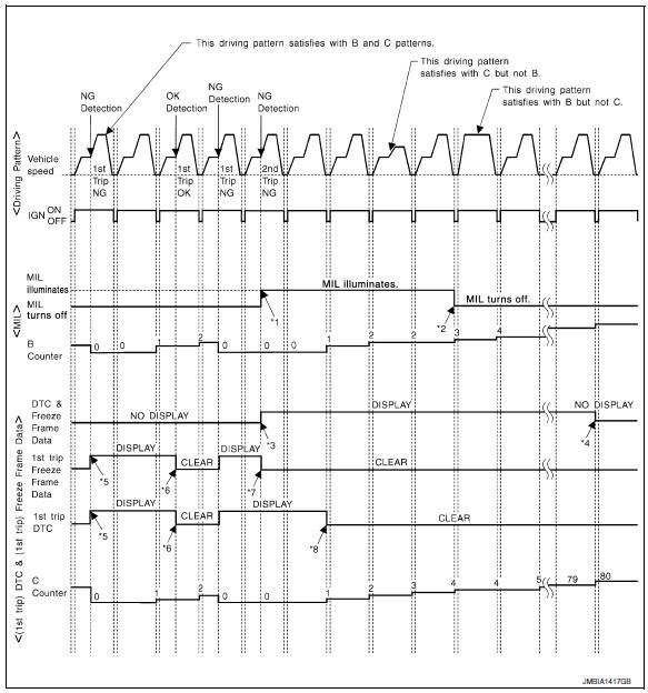
- When the same malfunction is detected in two consecutive trips, MIL will light up.
- MIL will turn OFF after vehicle is driven 3 times (pattern B) without any malfunctions.
- When the same malfunction is detected in two consecutive trips, the DTC and the freeze frame data will be stored in ECM.
- The DTC and the freeze frame data will not be displayed any longer after vehicle is driven 80 times (pattern C) without the same malfunction. (The DTC and the freeze frame data still remain in ECM.)
- When a malfunction is detected for the first time, the 1st trip DTC and the 1st trip freeze frame data will be stored in ECM.
- The 1st trip DTC and the 1st trip freeze frame data will be cleared at the moment OK is detected.
- When the same malfunction is detected in the 2nd trip, the 1st trip freeze frame data will be cleared.
- 1st trip DTC will be cleared when vehicle is driven once (pattern C) without the same malfunction after DTC is stored in ECM.
Explanation for Driving Patterns for “Misfire <Exhaust Quality Deterioration>”, “Fuel Injection System”
Driving Pattern B
Refer to EC-60, "DIAGNOSIS DESCRIPTION : Driving Pattern".
Driving Pattern C
Refer to EC-60, "DIAGNOSIS DESCRIPTION : Driving Pattern".
Example: If the stored freeze frame data is as per the following: Engine speed: 850 rpm, Calculated load value: 30%, Engine coolant temperature: 80°C (176°F) To be satisfied with driving pattern C, the vehicle should run under the following conditions: Engine speed: 475 – 1,225 rpm, Calculated load value: 27 – 33%, Engine coolant temperature: more than 70°C (158°F) Relationship Between MIL, DTC, 1st Trip DTC and Driving Patterns Except For “Misfire <Exhaust Quality Deterioration>”, “Fuel Injection System”
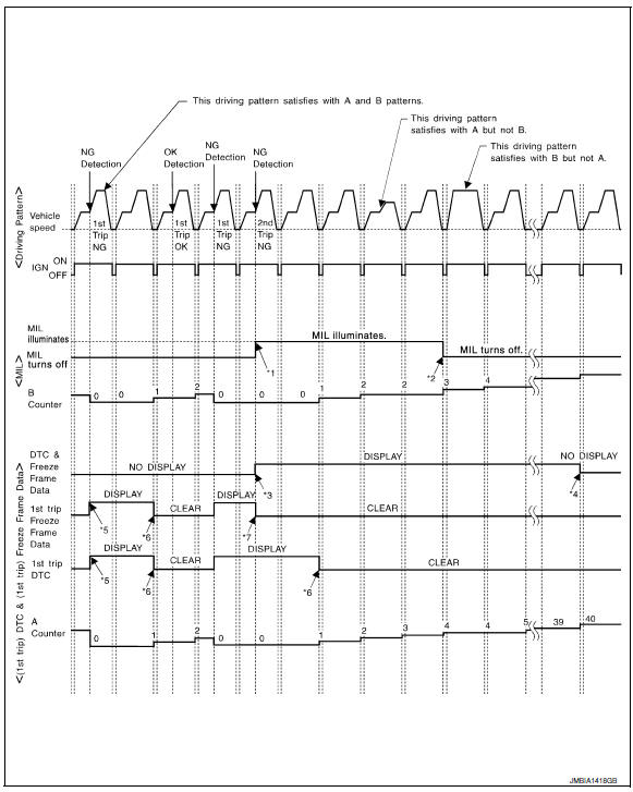
- When the same malfunction is detected in two consecutive trips, MIL will light up.
- MIL will turn OFF after vehicle is driven 3 times (pattern B) without any malfunctions.
- When the same malfunction is detected in two consecutive trips, the DTC and the freeze frame data will be stored in ECM.
- The DTC and the freeze frame data
will not be displayed any longer after
vehicle is driven 40 times (pattern A)
without the same malfunction.
(The DTC and the freeze frame data still remain in ECM.)
- When a malfunction is detected for the first time, the 1st trip DTC and the 1st trip freeze frame data will be stored in ECM.
- 1st trip DTC will be cleared after vehicle is driven once (pattern B) without the same malfunction.
- When the same malfunction is detected in the 2nd trip, the 1st trip freeze frame data will be cleared.
Explanation for Driving Patterns Except for “Misfire <Exhaust Quality Deterioration>”, “Fuel Injection System”
Driving Pattern A
Refer to EC-60, "DIAGNOSIS DESCRIPTION : Driving Pattern".
Driving Pattern B
Refer to EC-60, "DIAGNOSIS DESCRIPTION : Driving Pattern".
 Diagnosis system (ECM)
Diagnosis description : 1st trip detection
logic and two trip detection logic
When a malfunction is detected for the first time, 1st trip DTC and 1st trip
Freeze Frame data are stored in the
ECM ...
 Diagnosis description : driving pattern
DRIVING PATTERN A
Driving pattern A means a trip satisfying the following conditions.
Engine speed reaches 400 rpm or more.
Engine coolant temperature rises by 20В°C (36В°F) or more after s ...
Other materials:
System description
Component parts
Component parts location
BCM (view with instrument panel removed)
ECM
IPDM E/R
Combination meter
Security indicator lamp
CVT shift selector (park position
switch) (view with center console removed)
Stop lamp switch
Push button ignition switch
NATS anten ...
Compressor
Exploded view
With air conditioning
Compressor
Front
Without air conditioning
A/c idler pulley
A/c idler pulley bracket
Compressor
Compressor : removal and installation
REMOVAL
Discharge the refrigerant. Refer to ha-23, "recycle refrigerant".
Remove the fr ...
P117A AIR Fuel ratio
DTC Logic
DTC DETECTION LOGIC
NOTE:
If DTC P117A is displayed with other DTC, first perform the trouble
diagnosis for the other DTC. Refer
to EC-94, "DTC Index".
DTC No.
CONSULT screen terms
(Trouble diagnosis content)
DTC detecting condition
Possible cause
...
