
Nissan Sentra Service Manual: Cowl top
Exploded view
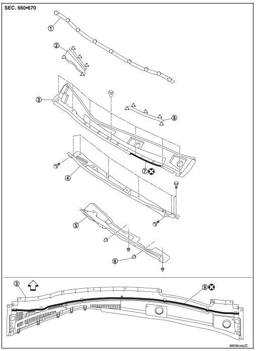
- Cowl top seal
- Cowl top grille cap
- Cowl top cover
- Cowl top extension
- Cowl top extension insulator
- Clip
- EPT seal [t: 3.0 mm (0.12 in)
- Cowl top cover cap
- EPT seal [t: 5.0 mm (0.20 in)]
 Pawl
 Clip
 Front
Removal and installation
COWL TOP COVER
Removal
- Remove front wiper arms (LH/RH). Refer to WW-57, "Removal and Installation".
- Remove front fender covers (LH/RH). Refer to DLK-159, "Exploded View".
- Remove front fender seals (LH/RH). Refer to DLK-306, "Exploded View".
- Remove cowl top cover clips.
- Pull forward to release cowl top cover from windshield glass.
CAUTION:
When performing the procedure after removing cowl top cover, cover the lower end of windshield glass with urethane etc.
- Remove cowl top cover.
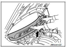
- Remove the following from the cowl top cover.
- EPT sealer
- Cowl top seal
- Cowl top grille cap
Installation
Installation is in the reverse order of removal.
CAUTION:
- Clean the joint between the cowl top cover and the windshield.
- Replace the EPT sealer on the back surface with new EPT sealer when reusing the cowl top cover.
- Remove the EPT sealer remaining on the cowl top cover using a double-faced adhesive tape remove.
- To maintain adhesion, do not wash the vehicle within 24 hours after installation.
- Perform the stop position adjustment at the installation of the front wiper arms.
Cowl Top Extension
Removal
- Remove the cowl top cover.
- Remove front wiper drive assembly. Refer to WW-62, "Removal and Installation".
- Remove cowl top extension bolts and cowl top extension.
- Remove cowl top extension insulator clips and cowl top extension insulator.
Installation
Installation is in the reverse order of removal.
 Front grille
Exploded view
Core support cover
Front grille
Emblem
Pawl
Removal and installation
REMOVAL
Remove core support cover bolts (A), clips (B) and core support
cover (1).
...
 Fender protector
Fender protector : exploded view
Front fender protector
Front wind deflector
U nut
Rivet
Grommet
Front
Fender protector : removal and installation - front f ...
Other materials:
Component parts
Engine control system
ENGINE CONTROL SYSTEM :Component Parts Location
Engine room compartment
No.
Component
Function
1
IPDM E/R
IPDM E/R control the internal relays and the actuators.
When CAN communication with ECM is impossible, IPDM
E/R performs fail-sa ...
P0327, P0328 KS
DTC Logic
DTC DETECTION LOGIC
DTC No.
CONSULT screen terms
(Trouble diagnosis content)
DTC detecting condition
Possible cause
P0327
KNOCK SEN/CIRC-B1
(Knock sensor 1 circuit
low bank 1)
An excessively low voltage from the knock sensor
is sent to ECM.
...
B0001, B0002 Driver airbag module
Description
DTC B0001, B0002 DRIVER AIRBAG MODULE
The driver air bag module is dual stage and is wired to the air bag diagnosis
sensor unit through the spiral
cable. The air bag diagnosis sensor unit will monitor for opens and shorts in
detected lines to the driver air bag
module including t ...
