Nissan Sentra Service Manual: Component parts
Component parts location
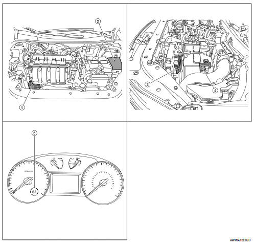
- Generator
- IPDM E/R (view with air inlet duct removed)
- ECM
- Battery current sensor
- Charge warning lamp indicator
Component description
| Component part | Description |
| Generator (IC regulator) | The IC regulator controls the power generation voltage
by the target
power generation voltage based on the received PWM command
signal.
When there is no PWM command signal, the generator performs the normal power generation according to the characteristic of the IC regulator. |
| IPDM E/R | The IPDM E/R converts the received power generation command value into a pulse width modulated (PWM) command signal and sends it to the IC regulator. |
| ECM | The battery current sensor detects the charging/discharging current
of the battery. The ECM judges the battery condition based on
this signal.
The ECM judges whether to request more output via the power generation voltage variable control according to the battery condition. When performing the power generation voltage variable control, the ECM calculates the target power generation voltage according to the battery condition and sends the calculated value as the power generation command value to the IPDM E/R. |
| Battery current sensor | The battery current sensor is located on the negative battery cable terminal. The battery current sensor detects the charging/discharging current of the battery and sends a voltage signal to the ECM according to the current value detected. |
| Combination meter (charge warning lamp) | The IC regulator warning function activates to illuminate the
charge warning lamp if any of the following symptoms occur while
generator is operating:
В·Excessive voltage is produced.
В·No voltage is produced. |

 Charging system
System Diagram
System Description
The generator provides DC voltage to operate the vehicle's electrical system
and to keep the battery charged.
The voltage output is controlled by the IC ...
Other materials:
Precaution for Supplemental Restraint System (SRS)
"AIR BAG" and "SEAT BELT PRE-TENSIONER"
The Supplemental Restraint System such as “AIR BAG” and “SEAT BELT PRE-TENSIONER”,
used along
with a front seat belt, helps to reduce the risk or severity of injury to the
driver and front passenger for certain
types of collision. Information necessary to service the system ...
Symptom diagnosis
Noise, vibration and harshness (NVH) troubleshooting
NVH troubleshooting chart
Locate the area where noise occurs.
Confirm the type of noise.
Specify the operating condition of engine.
Check specified noise source.
If necessary, repair or replace these parts.
Closely relate ...
Passenger compartment
CAUTION
Never use a fuse of a higher or lower
amperage rating than specified on the
fuse box cover. This could damage the
electrical system or cause a fire.
If any electrical equipment does not operate,
check for an open fuse.
NOTE:
The fuse box is located on the driver’s side
of the ...
