Nissan Sentra Service Manual: Component parts
Component parts location
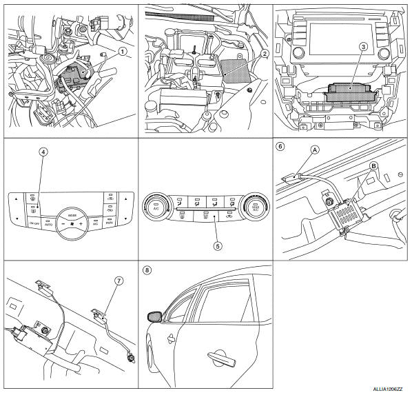
- Bcm (view with instrument panel removed)
- Ipdm e/r (rear window defogger relay)
- A/c auto amp. (View with a/c switch assembly removed)
- A/C switch assembly (rear window defogger switch) (with auto A/C)
- A/c switch assembly (rear window defogger switch) (without auto a/c)
- A. Rear window defogger power connector b. Condenser (view with rear pillar finisher lh removed)
- Rear window defogger ground connector (view with rear pillar finisher rh removed)
- Door mirror lh (door mirror defogger) (if equipped) (rh similar)
Component description
| Component | Description |
| BCM |
|
| Rear window defogger relay |
|
| A/c auto amp |
|
| A/c switch assembly (rear window defogger switch) |
|
| Rear window defogger |
|
| Door mirror defogger1 |
|
1: With heated mirrors

 System
System Description
Operation description
A/C control transmits rear window defogger switch signal to A/C auto
amp. when rear window defogger
switch turns ON while ignition switch is ON.
...
Other materials:
Intake manifold tuning system
INTAKE MANIFOLD TUNING SYSTEM : System
Description
SYSTEM DIAGRAM
SYSTEM DESCRIPTION
This system switches the length of intake air path according to the
low-to-medium speed range or high speed
range. Torque is increased in the low-to-medium speed range and the engine
output is improved ...
Wheel side
WHEEL SIDE : Removal and Installation
REMOVAL
Remove the wheel and tire using power tool. Refer to WT-47, "Exploded
View".
Remove the brake caliper torque member bolts, leaving the brake hose
attached. Position the brake caliper
aside with wire. Refer to BR-41, "BRAKE C ...
ECO mode switch
ECO mode switch
The ECO mode helps to enhance the fuel
economy by controlling the throttle sensitivity and
transmission points (CVT if so equipped).
To turn on the ECO mode, push the ECO mode
switch. The ECO mode indicator light (on the
speedometer) will remain lit while the mode is
act ...
