Nissan Sentra Service Manual: Clutch piping
Exploded View
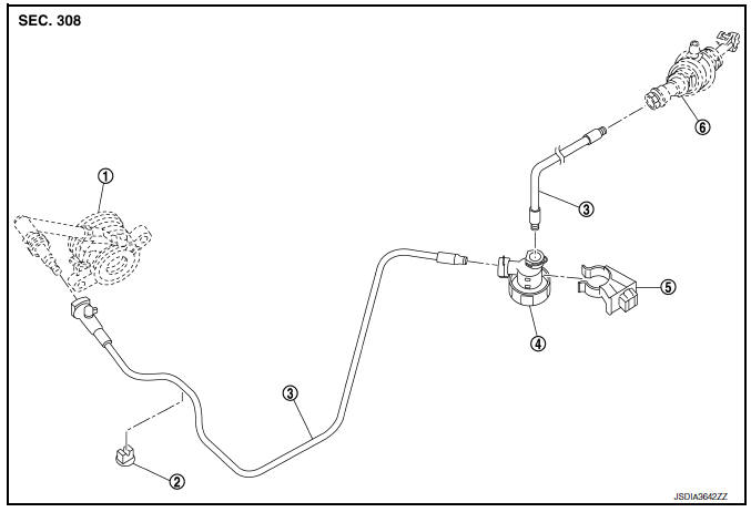
- CSC (Concentric Slave Cylinder)
- Clip
- Clutch tube
- Clutch damper
- Bracket
- Clutch master cylinder
Hydraulic Layout
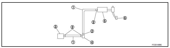
- Clutch tube
- Lock pin
- CSC (Concentric Slave Cylinder)
- Clutch damper
- Clutch master cylinder
- Clutch pedal
Removal and Installation
CAUTION:
Keep painted surface on the body or other parts free of clutch fluid. If it spills, wipe up immediately and wash the affected area with water.
NOTE:
When removing components such as hoses, tubes/lines, etc., cap or plug openings to prevent fluid from spilling.
REMOVAL
- Drain clutch fluid. Refer to CL-7, "Draining".
- Press the lock pin into the bleeding connector of the CSC, and then remove clutch tube from CSC.
- Pull outward on the lock pins from the connectors of the clutch damper until the pins stop, and then remove clutch tubes from clutch damper.
- Pull outward on the lock pin from the connector of the clutch master cylinder until the pin stops, and then remove clutch tube from clutch master cylinder.
INSTALLATION
Installation is in the reverse order of removal.
CAUTION:
Do not damage clutch tube.
- Insert each clutch tube into the CSC bleeding connector, the clutch damper connector, and the clutch master cylinder connector until it contacts the end of each connector
- Install each lock pin into the clutch damper connector and the clutch master cylinder connector until it contacts the end of each connector.
Inspection and Adjustment
INSPECTION AFTER REMOVAL
- Check the clutch tube for cracks and damage. If the clutch tube has cracks or damage, replace it with a new one.
- Check the O-ring of the clutch tube for cracks and damage. If the O-ring of the clutch tube has cracks or damage, replace clutch tube with a new one.
CAUTION:
Do not reuse O-rings.
- Check the clutch damper for cracks and damage. If the clutch damper has cracks or damage, replace it with a new one.
INSPECTION AFTER INSTALLATION
- Check the fluid leakage and the fluid level. Refer to CL-7, "Inspection".
- Check the clutch pedal height. Refer to CL-5, "Inspection and Adjustment".
ADJUSTMENT AFTER INSTALLATION
Perform the air bleeding procedure. Refer to CL-9, "Air Bleeding".
 Clutch master cylinder
Exploded View
Reservoir hose
Reservoir tank
Clutch master cylinder
Removal and Installation
REMOVAL
CAUTION:
Keep painted surface on the body or other parts free of clutch
flui ...
 CSC(concentric slave cylinder)
Exploded View
Transaxle assembly
CSC (Concentric Slave Cylinder)
Removal and Installation
CAUTION:
Do not reuse CSC (Concentric Slave Cylinder). The CSC slides back
to the origina ...
Other materials:
P0705 Transmission range sensor A
DTC Logic
DTC DETECTION LOGIC
DTC
CONSULT screen terms
[Trouble diagnosis content]
DTC detection condition
Possible causes
P0705
T/M RANGE SENSOR A
[Transmission Range Sensor
A Circuit (PRNDL Input)]
Two or more range signals simultaneously
stay ON conti ...
Periodic maintenance
In-cabin microfilter
Exploded View
Removal and Installation
REMOVAL
Remove the in-cabin microfilter cover.
CAUTION:
Before removing the in-cabin micofilter cover, let the vehicle rest for
at least 30 minutes.
Release the filter cover tab (A), then pull the bottom of the in-cabi ...
ECO mode switch
ECO mode switch
The ECO mode helps to enhance the fuel
economy by controlling the throttle sensitivity and
transmission points (CVT if so equipped).
To turn on the ECO mode, push the ECO mode
switch. The ECO mode indicator light (on the
speedometer) will remain lit while the mode is
act ...
