Nissan Sentra Service Manual: Clutch master cylinder
Exploded View
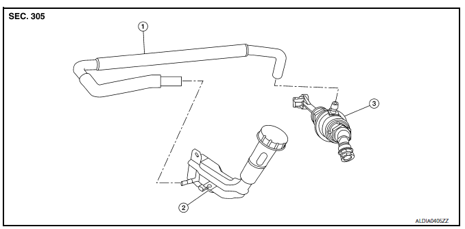
- Reservoir hose
- Reservoir tank
- Clutch master cylinder
Removal and Installation
REMOVAL
CAUTION:
- Keep painted surface on the body or other parts free of clutch fluid. If it spills, wipe up immediately and wash the affected area with water.
- Do not disassemble clutch master cylinder.
NOTE:
When removing components such as hoses, tubes/lines, etc., cap or plug openings to prevent fluid from spilling.
- Drain clutch fluid. Refer to CL-7, "Draining".
- Remove air cleaner body assembly. Refer to EM-25, "Removal and Installation".
- Remove reservoir hose from reservoir tank and clutch master cylinder.
- Remove clutch master cylinder rod end (

) from clutch pedal.
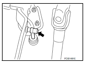
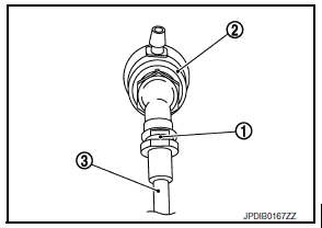
- Pull up the lock pin (1) from connector of clutch master cylinder (2) and separate clutch tube (3).
- Rotate clutch master cylinder clockwise by 45 degrees, and then remove clutch master cylinder from the vehicle.
INSTALLATION
CAUTION:
Keep painted surface on the body or other parts free of clutch fluid. If it spills, wipe up immediately and wash the affected area with water.
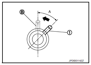
- With the nipple (1) rotated clockwise by 45 degrees, insert clutch mastery cylinder into the mounting hole. Rotate the clutch master cylinder counterclockwise by 45 degrees (A) as show to secure it. At this time, nipple (1) is in the upward (B) position.
- Install clutch master cylinder rod end to clutch pedal.
CAUTION:
Press clutch master cylinder rod end into clutch pedal until it stops.
- Install reservoir hose to reservoir tank and clutch master cylinder.
CAUTION:
Rotate reservoir hose with painted mark facing upward.
- Press down the lock pin into connector of clutch master cylinder until it stops.
- Install clutch tube into connector of clutch master cylinder until it stops.
- Fill with clutch fluid and perform air bleeding procedure. Refer to CL-8, "Refilling" and CL-9, "Air Bleeding".
- Installation of the remaining components is in the reverse order of removal.
Inspection and Adjustment
INSPECTION AFTER INSTALLATION
- Check for fluid leakage and the fluid level. Refer to CL-7, "Inspection".
- Check the clutch pedal height. Refer to CL-5, "Inspection and Adjustment".
- Check the clutch interlock switch position (if equipped). Refer to CL-5, "Inspection and Adjustment".
- Check the clutch pedal position switch position (if equipped). Refer to CL-5, "Inspection and Adjustment".
ADJUSTMENT AFTER INSTALLATION
- Adjust the clutch interlock switch position (if equipped). Refer to CL-5, "Inspection and Adjustment".
- Adjust the clutch pedal position switch position (if equipped). Refer to CL-5, "Inspection and Adjustment".
- Perform the air bleeding procedure. Refer to CL-9, "Air Bleeding".
 Clutch pedal
Exploded View
Clutch pedal
Stopper rubber
Clip
Clutch interlock switch (if equipped)
Clutch pedal position switch (if equipped)
Pedal pad
Pedal stopper rubber
Removal and Instal ...
 Clutch piping
Exploded View
CSC (Concentric Slave Cylinder)
Clip
Clutch tube
Clutch damper
Bracket
Clutch master cylinder
Hydraulic Layout
Clutch tube
Lock pin
CSC (Concentric Slav ...
Other materials:
Rear door glass
Removal and Installation
REMOVAL
NOTE:
LH rear door panel shown; RH similar.
Remove the rear door finisher. Refer to INT-19, "Removal and
Installation".
Remove the vapor barrier.
CAUTION:
Use care to not damage or tear vapor barrier during removal.
Remove the rear door ...
Ipdm-e branch line circuit
Diagnosis procedure
1.Check connector
Turn the ignition switch OFF.
Disconnect the battery cable from the negative terminal.
Check the terminals and connectors of the IPDM E/R for damage, bend and
loose connection (unit side
and connector side).
Is the inspection result normal?
Yes ...
Oil filter
Removal and Installation
REMOVAL
Remove engine under cover. Refer to EXT-16, "Exploded View".
Drain engine oil. Refer to LU-8, "Draining".
Remove the oil filter using Tool (A) as shown.
: Front
Tool number : KV10115801 (J-38956)
WARNING:
Be careful not to burn you ...
