
Nissan Sentra Service Manual: Clutch pedal
Exploded View
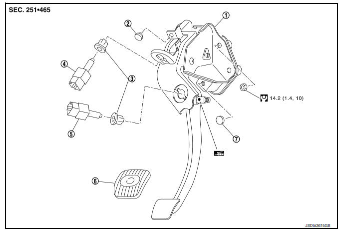
- Clutch pedal
- Stopper rubber
- Clip
- Clutch interlock switch (if equipped)
- Clutch pedal position switch (if equipped)
- Pedal pad
- Pedal stopper rubber
Removal and Installation
REMOVAL
- Remove instrument lower panel LH. Refer to IP-21, "Removal and Installation".
- Disconnect the harness connector from the clutch pedal position switch (if equipped).
- Disconnect the harness connector from the clutch interlock switch (if equipped).
- Disconnect clip of harness from clutch pedal.
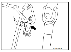
- Remove clutch master cylinder rod end from clutch pedal.
- Remove clutch pedal position switch and clip from clutch pedal (if equipped).
- Remove clutch interlock switch and clip from clutch pedal (if equipped).
- Remove clutch pedal from the vehicle
- Remove pedal pad from clutch pedal.
- Remove stopper rubber and pedal stopper rubber from clutch pedal, using a suitable remover.
INSTALLATION
Installation is in the reverse order of removal.
CAUTION:
After applying recommended grease, press clutch master cylinder rod end into clutch pedal until it stops.
Inspection and Adjustment
INSPECTION AFTER REMOVAL
- Check clutch pedal for bend, damage, or a cracked weld. If bend, damage, or a cracked weld is found, replace clutch pedal.
- Check pedal stopper rubber (if equipped). If damage or deformation is
found, replace pedal stopper rubber.
(if equipped)
- Check stopper rubber. If damage or deformation is found, replace stopper rubber.
- Check pedal pad. If wear or damage is found, replace pedal pad.
INSPECTION AFTER INSTALLATION
- Check the height of clutch pedal. Refer to CL-5, "Inspection and Adjustment".
- Check the clutch interlock switch position (if equipped). Refer to CL-5, "Inspection and Adjustment".
- Check the clutch pedal position switch position (if equipped). Refer to CL-5, "Inspection and Adjustment".
ADJUSTMENT AFTER INSTALLATION
- Adjust the clutch interlock switch position (if equipped). Refer to CL-5, "Inspection and Adjustment".
- Adjust the clutch pedal position switch position (if equipped). Refer to CL-5, "Inspection and Adjustment".

 Clutch master cylinder
Exploded View
Reservoir hose
Reservoir tank
Clutch master cylinder
Removal and Installation
REMOVAL
CAUTION:
Keep painted surface on the body or other parts free of clutch
flui ...
Other materials:
Exterior front
Engine hood
Windshield wiper and washer switch,
Windshield
Moonroof (if so equipped)
Power windows
Door locks, keyfob, keys, NISSAN
Intelligent Key® (if so equipped)
Mirrors
Tire pressure
Flat tire
Tire chains
Replacing bulbs
Headlight and turn signal switch, LED
he ...
How to read the displayed lines
Guiding lines which indicate the vehicle width
and distances to objects with reference to the
vehicle body line A are displayed on the monitor.
Distance guide lines:
Indicate distances from the vehicle body.
Red line 1 : approx. 1.5 ft (0.5 m)
Yellow line 2 : approx. 3 ft (1 m)
Green ...
Brake pedal
Exploded View
WITHOUT BRAKE PEDAL POSITION SWITCH
Snap pin
Brake pedal assembly
Brake pedal pad
Stop lamp switch
Clip
Clevis pin
Apply multi-purpose grease.
WITH BRAKE PEDAL POSITION SWITCH
Snap pin
Brake pedal assembly
Brake pedal pad
Brake pedal position switch
...
