Nissan Sentra Service Manual: Can communication circuit
Diagnosis procedure
1.Connector inspection
- Turn the ignition switch OFF.
- Disconnect the battery cable from the negative terminal.
- Disconnect all the unit connectors on can communication system.
- Check terminals and connectors for damage, bend and loose connection.
Is the inspection result normal? YES >> GO TO 2.
NO >> Repair the terminal and connector.
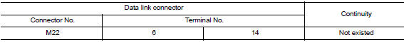
2.Check harness continuity (short circuit)
Check the continuity between the data link connector terminals.
Is the inspection result normal? Yes >> go to 3.
No >> check the harness and repair the root cause.
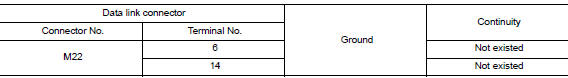
3.Check harness continuity (short circuit)
Check the continuity between the data link connector and the ground.
Is the inspection result normal? YES >> GO TO 4.
NO >> Check the harness and repair the root cause.
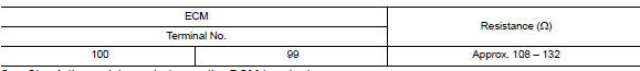
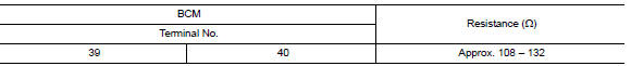
4.Check ecm and bcm termination circuit
- Remove the ECM and the BCM.
- Check the resistance between the ecm terminals.
- Check the resistance between the bcm terminals.
Is the measurement value within the specification? Yes >> go to 5.
No >> replace the ecm and/or the bcm.
5.Check symptom
Connect all the connectors. Check if the symptoms described in the “symptom (results from interview with customer)” are reproduced.
Inspection result
Reproduced>>go to 6.
Non-reproduced>>start the diagnosis again. Follow the trouble diagnosis procedure when past error is detected.
6.Check unit reproduction
Perform the reproduction test as per the following procedure for each unit.
- Turn the ignition switch off
- Disconnect the battery cable from the negative terminal.
- Disconnect one of the unit connectors of can communication system.
Note:
Ecm and bcm have a termination circuit. Check other units first.
- Connect the battery cable to the negative terminal. Check if the symptoms described in the “symptom (results from interview with customer)” are reproduced.
Note:
Although unit-related error symptoms occur, do not confuse them with other symptoms.
Inspection result
Reproduced>>connect the connector. Check other units as per the above procedure.
Non-reproduced>>replace the unit whose connector was disconnected.
 Bcm branch line circuit
Diagnosis procedure
1.Check connector
Turn the ignition switch off.
Disconnect the battery cable from the negative terminal.
Check the terminals and connectors of the BCM for damage, bend and ...
 Can system (type 3)
Dtc/circuit diagnosis ...
Other materials:
Service
Never use electrical test equipment to check SRS circuits unless
instructed to in this Service Manual.
Before servicing the SRS, turn power switch OFF, disconnect battery
negative terminal and wait 3 minutes
or more.
For approximately 3 minutes after the cables are removed, it is stil ...
Rear-facing child restraint installation using the seat belts
WARNINGThe three-point seat belt with Automatic
Locking Retractor (ALR) must be used
when installing a child restraint. Failure to
use the ALR mode will result in the child
restraint not being properly secured. The
restraint could tip over or be loose and
cause injury to ...
Brake master cylinder
Exploded View
Reservoir cap
Oil strainer
Reservoir tank
Cylinder body
Pin
O-ring
Grommet
Apply brake fluid
PBC (Poly Butyl Cuprysil)
grease or
silicone-based grease
Removal and Installation
REMOVAL
CAUTION:
Do not spill or splash brake fluid on painted surfaces. ...
