Nissan Sentra Service Manual: C1708, C1709, C1710, C1711 Transmitter (no data)
DTC Logic
NOTE:
The Signal Tech II Tool (J-50190) can be used to perform the following functions. Refer to the Signal Tech II User Guide for additional information.
- Activate and display TPMS transmitter IDs
- Display tire pressure reported by the TPMS transmitter
- Read TPMS DTCs
- Register TPMS transmitter IDs
DTC DETECTION LOGIC
| DTC | Display Item | Malfunction detected condition | Possible causes |
| C1708 | [NO DATA] FL | Tire pressure data signal from the front LH wheel transmitter cannot be detected. |
|
| C1709 | [NO DATA] FR | Tire pressure data signal from the front RH wheel transmitter cannot be detected. | |
| C1710 | [NO DATA] RR | Tire pressure data signal from the rear RH wheel transmitter cannot be detected. | |
| C1711 | [NO DATA] RL | Tire pressure data signal from the rear LH wheel transmitter cannot be detected. |
DTC CONFIRMATION PROCEDURE
1.PERFORM SELF DIAGNOSTIC RESULT
 With CONSULT
- Drive for 3 minutes at a speed of 40 km/h (25 MPH) or more, then drive normally for 10 minutes.
- Stop the vehicle.
- Perform “SELF DIAGNOSTIC RESULT”.
Is DTC “C1708”, “C1709”, “C1710” or “C1711” detected? YES >> Proceed to WT-27, "Diagnosis Procedure".
NO >> Inspection End.
Diagnosis Procedure
NOTE:
The Signal Tech II Tool (J-50190) can be used to perform the following functions. Refer to the Signal Tech II User Guide for additional information.
- Activate and display TPMS transmitter IDs
- Display tire pressure reported by the TPMS transmitter
- Read TPMS DTCs
- Register TPMS transmitter IDs
Regarding Wiring Diagram information, refer to WT-15, "WITH INTELLIGENT KEY : Wiring Diagram" or WT- 18, "WITHOUT INTELLIGENT KEY : Wiring Diagram".
1.CHECK DATA MONITOR
 With CONSULT
- Drive for 3 minutes at a speed of 40 km/h (25 MPH) or more, then drive normally for 10 minutes.
- Stop the vehicle.
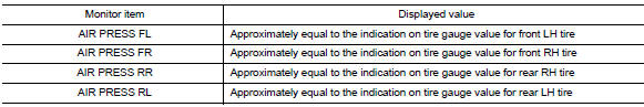
- On “DATA MONITOR” select “AIR PRESS FL”, “AIR PRESS FR”, “AIR PRESS RR” and “AIR PRESS RL”.
- Within 5 minutes after vehicle is stopped, read the values displayed on CONSULT
Are all tire pressures displayed 0 kPa (psi)? YES >> GO TO 2.
NO >> GO TO 5.
2.CHECK REMOTE KEYLESS ENTRY RECEIVER POWER CIRCUIT
Check voltage between remote keyless entry receiver connector and ground.
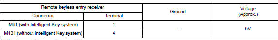
Is the inspection result normal?
YES >> GO TO 3.
NO >> Repair or replace harness or connectors.
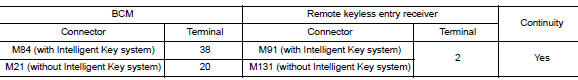
3.Check remote keyless entry receiver signal circuit
- Turn the ignition switch OFF.
- Disconnect BCM and remote keyless entry receiver connectors.
- Check continuity between BCM and remote keyless entry receiver connectors.
- Check continuity between BCM connector and ground.
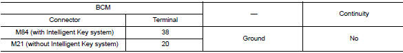
Is the inspection result normal? YES >> GO TO 4.
NO >> Repair or replace the malfunctioning harness or connector.
4.Check remote keyless entry receiver ground circuit
Check continuity between BCM and remote keyless entry receiver connectors.
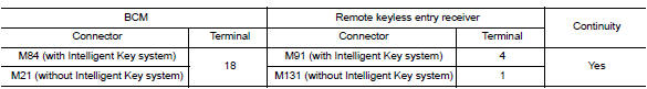
Is the inspection result normal? YES >> GO TO 5.
NO >> Repair or replace the malfunctioning harness or connector.
5.Transmitter id registration
Perform transmitter ID registration. Refer to WT-22, "Work Procedure".
Can the tire pressure sensor ID registration be completed? YES >> GO TO 6.
NO >> Replace applicable transmitter. Refer to WT-50, "Removal and Installation".
6.Check tire pressure signal
 With CONSULT
- Drive for 3 minutes at a speed of 40 km/h (25 MPH) or more, then drive normally for 10 minutes.
- Stop the vehicle.
- On “DATA MONITOR” select “AIR PRESS FL”, “AIR PRESS FR”, “AIR PRESS RR” and “AIR PRESS RL”.
- Within 5 minutes after vehicle stopped, check that the tire pressures are within specification. Refer to WT- 54, "Tire Air Pressure".
Is the inspection result normal? YES >> Inspection End.
NO >> Replace the BCM. Refer to BCS-73, "Removal and Installation" (with Intelligent Key system) or BCS-126, "Removal and Installation" (without Intelligent Key system).
 C1704, C1705, C1706, C1707 Low tire pressure
DTC Logic
NOTE:
The Signal Tech II Tool (J-50190) can be used to perform the following
functions. Refer to the Signal Tech II
User Guide for additional information.
Activate and display TPMS ...
 C1716, C1717, C1718, C1719 Transmitter (pressure data)
DTC Logic
NOTE:
The Signal Tech II Tool (J-50190) can be used to perform the following
functions. Refer to the Signal Tech II
User Guide for additional information.
Activate and display TPMS ...
Other materials:
Precaution for Harness Repair
Solder the repair part, and wrap it with tape. [Twisted wire
fray
must be 110 mm (4.33 in) or less.]
Do not bypass the repair point with wire. (If it is
bypassed, the turnout
point cannot be separated and the twisted wire characteristics
are lost.)
...
Precaution for Seat Belt Service
CAUTION:
Before removing the seat belt pre-tensioner assembly, turn the
ignition switch OFF, disconnect both
battery terminals and wait at least three minutes. For approximately three
minutes after the battery
terminals have been removed, it is still possible for the air bag and seat
...
Front seat belt
Exploded View
D-ring anchor
Seat belt height adjuster cover
Seat belt buckle
Seat belt retractor
Seat belt height adjuster
Lap belt pre-tensioner harness
connector
Shoulder belt pre-tensioner
harness connector
Front
NOTE:
LH side shown; RH side similar.
Removal an ...
