Nissan Sentra Service Manual: C1601 Battery power supply
DTC Logic
DTC DETECTION LOGIC
| DTC | Display item | Malfunction detected condition | Possible cause |
| C1601 | BATTERY VOLT | When a power supply voltage to the EPS control unit is maintained at 17.5 V or more or at less than 9 V continuously for five second or more. |
|
DTC CONFIRMATION PROCEDURE
1.PRECONDITIONING
If DTC CONFIRMATION PROCEDURE has been previously conducted, always turn ignition switch OFF and wait at least 10 seconds before conducting the next test.
>> GO TO 2.
2.DTC REPRODUCTION PROCEDURE
 With CONSULT
-
Turn the ignition switch OFF to ON.
-
Perform EPS self-diagnosis.
Is DTC C1601 detected? YES >> Proceed to diagnosis procedure. Refer to STC-22, "Diagnosis Procedure".
NO >> Inspection End.
Diagnosis Procedure
Regarding Wiring Diagram information, refer to STC-15, "Wiring Diagram".
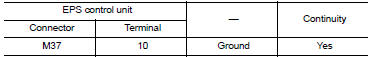
1.Check EPS Control unit ground circuit
-
Turn ignition switch OFF.
-
Disconnect EPS control unit harness connector.
-
Check continuity between EPS control unit harness connector terminal and ground.
-
Connect EPS control unit harness connector.
Is the inspection result normal? YES >> GO TO 2.
NO >> Repair open circuit or short to ground or short to power in harness or connectors.
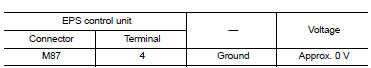
2.Check EPS Control unit power supply circuit (1)
-
Check voltage between EPS control unit harness connector terminals and ground.
Is the inspection result normal? YES >> GO TO 4.
NO >> GO TO 3.
3.Check EPS Control unit power supply circuit
(2)
-
Turn ignition switch OFF.
-
Check the 10A fuse (#5).
-
Check the harness for open or short between EPS control unit harness connector terminal 4 and the 10A fuse (#5).
Is the inspection result normal? YES >> Perform the trouble diagnosis for ignition power supply circuit. Refer to PCS-70, "Wiring Diagram".
NO >> Repair or replace the malfunctioning parts.
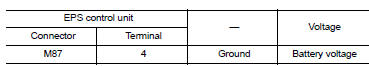
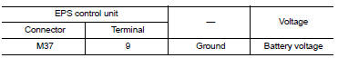
4.Check EPS Control unit power supply circuit (3)
-
Turn ignition switch OFF.
-
Check voltage between EPS control unit harness connector terminals and ground.
-
Turn ignition switch ON.
CAUTION:
Never start the engine.
-
Check voltage between EPS control unit harness connector and ground.
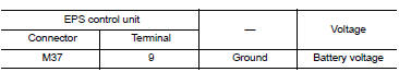
Is the inspection result normal? YES >> GO TO 6.
NO >> GO TO 5.
5.CHECK EPS CONTROL UNIT POWER SUPPLY CIRCUIT (4)
-
Turn ignition switch OFF.
-
Check the 60A fusible link (#M).
-
Check the harness for open or short between EPS control unit harness connector terminal 9 and the 60A fusible link (#M).
Is the inspection result normal? YES >> Perform the trouble diagnosis for power supply circuit. Refer to PCS-70, "Wiring Diagram".
NO >> Repair or replace the malfunctioning parts.
6.CHECK TERMINALS AND HARNESS CONNECTORS
Check the EPS control unit pin terminals for damage or loose connection with harness connector.
Is the inspection result normal? YES >> EPS control unit is malfunctioning. Replace steering column assembly. Refer to ST-12, "Removal and Installation".
NO >> Repair or replace the malfunctioning parts.

 C1604 Torque sensor
DTC Logic
DTC DETECTION LOGIC
DTC
Display item
Malfunction detected condition
Possible cause
C1604
TORQUE SENSOR
When torque sensor output signal is malfunctioning
...
Other materials:
Front wiper motor hi circuit
Component function check
1. Check front wiper hi operation
Ipdm e/r auto active test
Start ipdm e/r auto active test. Refer to ww-15, "diagnosis description"
(with intelligent key system) or
ww-19, "diagnosis description" (without intelligent key system).
Check tha ...
Diagnosis system (bcm) (with intelligent key system)
Common item
COMMON ITEM : CONSULT Function (BCM - COMMON ITEM)
APPLICATION ITEM
CONSULT performs the following functions via CAN communication with BCM.
Direct Diagnostic Mode
Description
ECU identification
The BCM part number is displayed.
Self Diagnostic Result
...
NISSAN Intelligent Key® (if so equipped)
Replace the battery in the Intelligent Key as follows:
Remove the mechanical key from the Intelligent
Key.
Insert a small screwdriver A into the slit B
of the corner and twist it to separate the
upper part from the lower part. Use a cloth to
protect the casing.
Replace the battery wi ...
