Nissan Sentra Service Manual: C1140 Actuator relay system
DTC Logic
DTC DETECTION LOGIC
| DTC | Display Item | Malfunction detected condition | Possible causes |
| C1140 | ACTUATOR RLY | When a malfunction is detected in actuator relay. |
|
DTC CONFIRMATION PROCEDURE
1.CHECK SELF DIAGNOSTIC RESULT
 With CONSULT
- Turn ignition switch ON.
- Perform self diagnostic result.
Is DTC C1140 detected? YES >> Proceed to diagnosis procedure. Refer to BRC-77, "Diagnosis Procedure".
NO >> Inspection End.
Diagnosis Procedure
Regarding Wiring Diagram information, refer to BRC-44, "Wiring Diagram".
1.CONNECTOR INSPECTION
-
Turn ignition switch OFF.
-
Disconnect ABS actuator and electric unit (control unit) connector.
-
Check connector and terminals for deformation, disconnection, looseness or damage.
Is the inspection result normal? YES >> GO TO 2.
NO >> Repair or replace as necessary.
2.Check ABS Actuator and electric unit (control unit) battery power supply
Check voltage between ABS actuator and electric unit (control unit) connector E33 terminal 25 and ground.
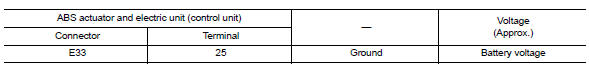
Is the inspection result normal? YES >> GO TO 3.
NO >> Repair or replace malfunctioning components.
3.Check abs actuator and electric unit (control unit) ground circuit
Check continuity between ABS actuator and electric unit (control unit) connector E33 terminals 13, 38 and ground.
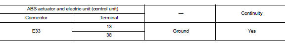
Is the inspection result normal? YES >> Replace ABS actuator and electric unit (control unit). Refer to BRC-110, "Removal and Installation".
NO >> Repair or replace malfunctioning components.
 C1130 Engine signal
DTC Logic
DTC DETECTION LOGIC
DTC
Display Item
Malfunction detected condition
Possible causes
C1130
ENGINE SIGNAL 1
When a malfunction is detected in ECM system.
...
 C1142 Press sensor
DTC Logic
DTC DETECTION LOGIC
DTC
Display Item
Malfunction detected condition
Possible causes
C1142
PRESS SEN CIRCUIT
When a malfunction is detected in master cylinde ...
Other materials:
Door mirror
Exploded view
Door mirror cover
(with side turn signal lamp)
Door mirror housing
Door mirror actuator
Glass mirror
Door mirror cover
(without side turn signal lamp)
: Pawl
Door mirror assembly
Door mirror assembly : removal and installation
Removal
Caution:
Be careful no ...
Front disc brake
BRAKE PAD
BRAKE PAD : Inspection
PAD WEAR
Check brake pad thickness from an inspection hole on caliper body.
Check using a scale if necessary
Wear limit thickness : Refer to BR-55, "Front Disc
Brake".
DISC ROTOR
DISC ROTOR : Inspection
APPEARANCE
Check surface of disc rotor ...
Basic inspection
Diagnosis and repair workflow
Work Flow
OVERALL SEQUENCE
DETAILED FLOW
1. OBTAIN INFORMATION ABOUT SYMPTOM
Interview the customer to obtain as much information as possible about the
conditions and environment under
which the malfunction occurred.
>> GO TO 2.
2. CONFIRM THE SYMPTO ...
