
Nissan Sentra Service Manual: Brake pedal
Exploded View
WITHOUT BRAKE PEDAL POSITION SWITCH
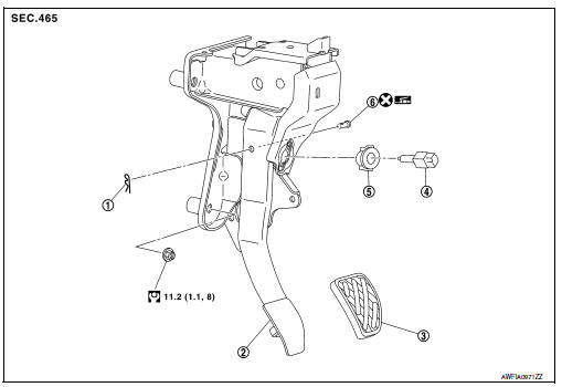
- Snap pin
- Brake pedal assembly
- Brake pedal pad
- Stop lamp switch
- Clip
- Clevis pin
 Apply multi-purpose grease.
WITH BRAKE PEDAL POSITION SWITCH
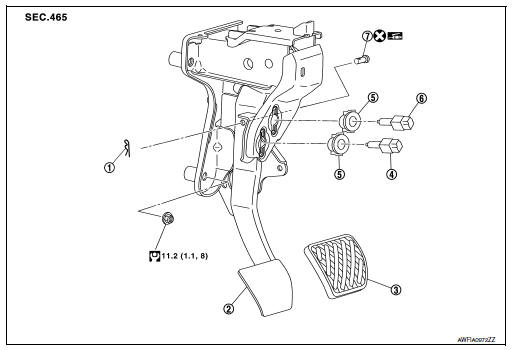
- Snap pin
- Brake pedal assembly
- Brake pedal pad
- Brake pedal position switch
- Clip
- Stop lamp switch
 Apply multi-purpose grease.
Removal and Installation
REMOVAL
- Remove instrument lower panel LH. Refer to IP-21, "Removal and Installation".
- Remove steering column lower cover. Refer to IP-16, "Removal and Installation".
- Disconnect the harness connectors from the brake pedal position switch (if equipped) and the stop lamp switch.
- Rotate the stop lamp switch and the brake pedal position switch (if equipped) (1) counter clockwise to remove.
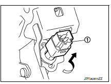
- Disconnect the accelerator pedal harness connector and harness clip.
- Remove snap pin and clevis pin from clevis on brake booster.
- Remove the brake pedal assembly.
CAUTION:
Secure the brake booster and brake master cylinder to avoid damage to components.
- Remove accelerator pedal from brake pedal assembly. Refer to ACC-3, "Removal and Installation".
INSPECTION AFTER REMOVAL
Check for the following items and replace the brake pedal assembly, if necessary.
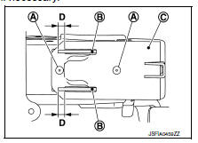
- Check the brake pedal upper rivet (A) for damage or wear.
- Check the brake pedal for bend, damage, and cracks on the welded parts.
- Check the lapping length (D) of sub-bracket (B) and slide plate (C).
Lapping length (D) : 6.5 mm (0.256 in) or more
INSTALLATION
Installation is in the reverse order of removal.
CAUTION:
- Do not reuse the clevis pin.
- Install the clevis pin in the proper direction. Refer to BR-22, "Exploded View".
- Apply multi-purpose grease to the clevis pin and the mating faces, if necessary.
ADJUSTMENT AFTER INSTALLATION
- Adjust each item of brake pedal after installing the brake pedal assembly to the vehicle. Refer to BR-15, "Adjustment".
- Perform the release position learning of the accelerator pedal. Refer to EC-138, "Work Procedure".

 Brake piping
FRONT
FRONT : Exploded View
Brake tube
ABS actuator and electric unit (control
unit)
Connector
Connector bracket
Master cylinder assembly
Brake booster
Lock plate
Brake hose
...
Other materials:
Precaution for Liquid Gasket
Removal of liquid gasket
After removing the bolts and nuts, separate the mating surface and
remove the old liquid gasket using tool.
Tool number : kv10111100 (j-37228)
Caution:
Do not damage the mating surfaces.
Tap the seal cutter to insert it (1).
In areas where the tool is diffic ...
Symptom diagnosis
Multi av system
Symptom table
Related to audio
Related to hands-free phone
Before performing diagnosis, confirm that the cellular phone being used
by the customer is compatible with
the vehicle.
It is possible that a malfunction is occurring due to a version change
of the ph ...
Primary speed sensor
Exploded View
Transaxle assembly
O-ring
Primary speed sensor
: Always replace after every
disassembly.
: N m (kg-m, in-lb)
: Genuine NISSAN CVT Fluid NS-3
Removal and Installation
REMOVAL
Disconnect the primary speed sensor connector.
Remove the primary speed sensor.
...
