Nissan Sentra Service Manual: Brake pedal
Adjustment
BRAKE PEDAL HEIGHT
- Remove instrument lower panel LH. Refer to IP-21, "Removal and Installation".
- Disconnect the harness connectors from the brake pedal position switch (if equipped) and the stop lamp switch.
- Turn the stop lamp switch and brake pedal position switch (if equipped) 45В° counterclockwise.
- Loosen the input rod lock nut (1). Adjust the brake pedal height to the specification.
CAUTION:
- Check the height with the floor trim removed.
- The threaded end of the input rod (2) must project to the inner side (L) of the clevis (3).
Brake pedal height (H1) : Refer to BR-54, "Brake Pedal".
- Tighten the input rod lock nut to specification. Refer to BR-34, "Exploded View".
- Check the brake pedal for smooth operation.
CAUTION:
The stop lamp must turn off when the brake pedal is released.
STOP LAMP SWITCH AND BRAKE PEDAL POSITION SWITCH
- Remove instrument lower panel LH. Refer to IP-21, "Removal and Installation".
- Disconnect the harness connectors from the brake pedal position switch (if equipped) and the stop lamp switch.
- Turn the stop lamp switch and brake pedal position switch (if equipped) 45В° counterclockwise.
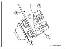
- With the threaded ends of the stop lamp switch (2) and brake
pedal position switch (if equipped) (1) contacting the pedal
bracket (3), turn the switches 45В° clockwise to lock in place.
Check that both the stop lamp switch (2) and brake pedal position switch (if equipped) (1) contact ends to brake pedal bracket (3) clearance (A) are within specification.
- CAUTION:
- Make sure that the clearance (A) between the brake pedal bracket (3), stop lamp switch (2) and the brake pedal position switch (1) contact ends are within specification.
- The stop lamp must turn off when the brake pedal is released.
Clearance (A) : Refer to BR-54, "Brake Pedal".

 Brake fluid
Drain and Refill
CAUTION:
Do not spill or splash brake fluid on painted surfaces. Brake
fluid may damage paint. If brake fluid is
splashed on painted areas, wash it away with water immediate ...
Other materials:
Component parts
Moonroof
Moonroof : component parts location
Bcm
(view under instrument panel, left side of
vehicle)
Moonroof switch
Moonroof motor assembly (view with
headliner removed)
Front door lock assembly lh (key cylinder
switch)
Front door switch lh (rh
similar)
Combination met ...
Eco mode control
ECO MODE CONTROL : System Description
SYSTEM DIAGRAM
SYSTEM DESCRIPTION
ECM receives an ECO mode signal from combination meter via CAN
communication and improves the fuel
economy by controlling the throttle movement to less than usual. Therefore,
driving characteristic is controlle ...
Liquid Gasket
REMOVAL OF LIQUID GASKET SEALING
After removing the bolts and nuts, separate the mating surface and
remove the liquid gasket using Tool (A).
Tool Number : KV10111100 (J-37228)
CAUTION:
Be careful not to damage the mating surfaces.
In areas where the cutter is difficult to use, use ...
