
Nissan Sentra Service Manual: Brake fluid
Drain and Refill
CAUTION:
- Do not spill or splash brake fluid on painted surfaces. Brake fluid may damage paint. If brake fluid is splashed on painted areas, wash it away with water immediately.
- Prior to repair, turn the ignition switch OFF, disconnect the ABS actuator and electric unit (control unit) connector or negative battery terminal. Refer to PG-50, "Exploded View".
- Refill brake system with new brake fluid. Refer to MA-11, "Fluids and Lubricants".
- Do not reuse drained brake fluid.
DRAINING
- Turn ignition switch OFF and disconnect ABS actuator and electric unit (control unit) connector or negative battery terminal. Refer to PG-50, "Exploded View".
- Connect a vinyl tube to bleeder valve.
- Depress brake pedal, loosen bleeder valve, and gradually remove brake fluid.
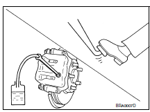
REFILLING
- Make sure no foreign material exists in the reservoir and refill with new brake fluid.
CAUTION:
Do not reuse drained brake fluid.
- Refill the brake system as follows:
- Depress the brake pedal.
- Loosen bleeder valve.
- Slowly depress brake pedal to 2/3 of the brake pedal full stroke.
- Tighten bleeder valve.
- Release brake pedal.
Repeat this operation at intervals of two or three seconds until all old brake fluid is discharged. Add new brake fluid to master cylinder reservoir sub tank frequently.
CAUTION:
Do not allow master cylinder reservoir to empty as this may cause damage to master cylinder internal components.
- Bleed the air out of the brake hydraulic system. Refer to BR-17, "Bleeding Brake System".
Bleeding Brake System
CAUTION:
Do not spill or splash brake fluid on painted surfaces. Brake fluid may damage paint. If brake fluid is splashed on painted areas, wash it away with water immediately.
While bleeding, pay attention to master cylinder fluid level.
Before working, disconnect ABS actuator and electric unit (control unit) connectors or negative battery terminal. Refer to PG-50, "Exploded View".
- Turn ignition switch OFF and disconnect ABS actuator and electric unit (control unit) connector or negative battery terminal. Refer to PG-50, "Exploded View".
- Connect a vinyl tube to rear right brake bleeder valve.
- Fully depress brake pedal 4 or 5 times.
- With brake pedal depressed, loosen bleeder valve to bleed air in brake line, and then tighten it immediately.
- Repeat steps 3 and 4 until all of the air is out of the brake line.
- Tighten the bleeder valve to the specified torque. Refer to BR-40, "BRAKE CALIPER ASSEMBLY : Exploded View" (front disc brake), BR-42, "Exploded View" (rear drum brake) BR-46, "BRAKE CALIPER ASSEMBLY : Exploded View" (rear disc brake).
- Repeat steps 2 through 6, with master cylinder reservoir tank filled at least halfway. Bleed the air in the following order: front right brake→ front left brake → rear right brake → rear left brake.
 Brake pedal
Adjustment
BRAKE PEDAL HEIGHT
Remove instrument lower panel LH. Refer to IP-21, "Removal and
Installation".
Disconnect the harness connectors from the brake pedal position switch
...
 Front disc brake
Brake Burnishing
CAUTION:
Burnish contact surfaces between brake pads and disc rotor
according to the following procedure
after refinishing the disc rotor, replacing brake pads or if a soft ...
Other materials:
Power supply and ground circuit
Av control unit
Av control unit : diagnosis procedure
Regarding wiring diagram information, refer to av-331, "wiring diagram".
1.Check fuse
Check that the following fuses are not blown.
Are the fuses blown?
Yes >> replace the blown fuse after repairing the affected circuit. ...
P0967 Pressure control solenoid B
DTC Logic
DTC DETECTION LOGIC
DTC
CONSULT screen terms
(Trouble diagnosis content)
DTC detection condition
Possible causes
P0967
PC SOLENOID B
(Pressure Control Solenoid B
Control Circuit High)
The primary pressure solenoid valve current is
200 mA or les ...
Operating range
The Intelligent Key functions can only be used
when the Intelligent Key is within the specified
operating range.
When the Intelligent Key battery is almost discharged
or strong radio waves are present near
the operating location, the Intelligent Key system’s
operating range becomes nar ...
