Nissan Sentra Service Manual: Adjustment of steering angle sensor neutral position
Description
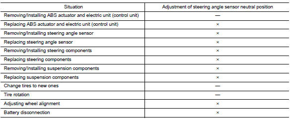
Refer to the table below to determine if adjustment of steering angle sensor neutral position is required.
×: Required –: Not required
Work Procedure
ADJUSTMENT OF STEERING ANGLE SENSOR NEUTRAL POSITION
CAUTION:
To adjust neutral position of steering angle sensor, make sure to use CONSULT.
(Adjustment cannot be done without CONSULT).
1.ALIGN THE VEHICLE STATUS
Stop vehicle with front wheels in straight-ahead position.
>> GO TO 2.
2.PERFORM THE NEUTRAL POSITION ADJUSTMENT FOR THE STEERING ANGLE SENSOR
-
On the CONSULT screen, touch “WORK SUPPORT” and “ST ANG SEN ADJUSTMENT” in order.
-
Touch “START”.
CAUTION:
Do not touch steering wheel while adjusting steering angle sensor.
-
After approximately 10 seconds, touch “END”.
NOTE:
After approximately 60 seconds, it ends automatically.
-
Turn ignition switch OFF, then turn it ON again.
CAUTION:
Be sure to perform above operation.
>> GO TO 3.
3.CHECK DATA MONITOR
-
Run vehicle with front wheels in straight-ahead position, then stop
-
Select “DATA MONITOR”. Then make sure “STR ANGLE SIG” is within 0±2.5°.
Is the steering angle within the specified range? YES >> GO TO 4.
NO >> Perform the neutral position adjustment for the steering angle sensor again, GO TO 1
4.ERASE THE SELF-DIAGNOSIS MEMORY
Erase the self-diagnosis memory of the ABS actuator and electric unit (control unit) and ECM.
-
ABS actuator and electric unit (control unit): Refer to BRC-31, "CONSULT Function (ABS)".
-
ECM: Refer to EC-66, "CONSULT Function".
Are the memories erased? YES >> Inspection End
NO >> Check the items indicated by the self-diagnosis.
 Diagnosis and repair work flow
Work Flow
OVERALL SEQUENCE
DETAILED FLOW
1.COLLECT INFORMATION FROM THE CUSTOMER
Get detailed information from the customer about the symptom
(the condition and the environment when the
in ...

Other materials:
Basic inspection
Diagnosis and repair workflow
Work flow
OVERALL SEQUENCE
DETAILED FLOW
1.INTERVIEW FOR MALFUNCTION
Find out what the customer's concerns are.
>> GO TO 2.
2.SYMPTOM CHECK
Verify the symptom from the customer's information.
>> GO TO 3.
3.BASIC INSPECTION
Check the operat ...
P0461 Fuel level sensor
DTC Logic
DTC DETECTION LOGIC
NOTE:
If DTC P0461 is displayed with DTC UXXXX, first perform the trouble
diagnosis for DTC UXXXX.
If DTC P0461 is displayed with DTC P0607, first perform the trouble
diagnosis for DTC P0607. Refer
to EC-350, "DTC Logic".
Driving long distan ...
Precaution
Precaution for supplemental restraint system (srs) "air bag" and "seat
belt pre-tensioner"
The supplemental restraint system such as “air bag” and “seat belt pre-tensioner”,
used along
with a front seat belt, helps to reduce the risk or severity of injur ...
