Nissan Sentra Service Manual: Diagnosis and repair work flow
Work Flow
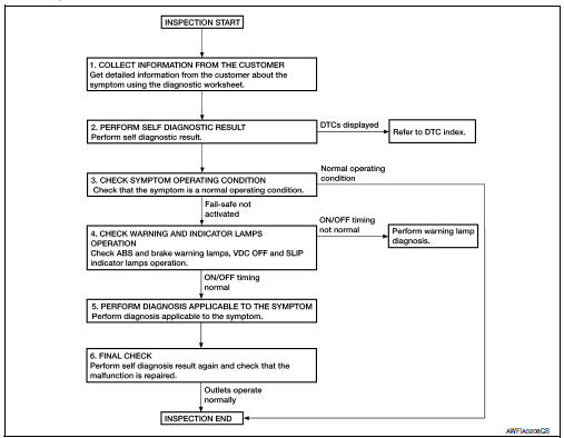
OVERALL SEQUENCE
DETAILED FLOW
1.COLLECT INFORMATION FROM THE CUSTOMER
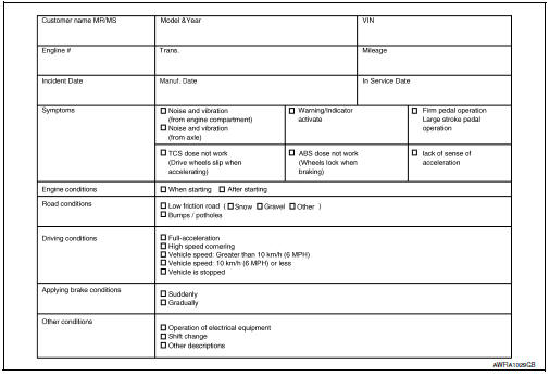
Get detailed information from the customer about the symptom (the condition and the environment when the incident/malfunction occurred) using the diagnostic worksheet. Refer to BRC-52, "Diagnostic Work Sheet".
>> GO TO 2.
2.PERFORM SELF DIAGNOSTIC RESULT
Perform self diagnostic result. Refer to BRC-31, "CONSULT Function (ABS)".
Are any DTCs displayed? YES >> Refer to BRC-43, "DTC Index".
NO >> GO TO 3.
3.CHECK SYMPTOM OPERATING CONDITION
Check that the symptom is a normal operating condition. Refer to BRC-105, "Description".
Is the symptom a normal operating condition? YES >> Inspection End.
NO >> GO TO 4.
4.CHECK WARNING AND INDICATOR LAMPS OPERATION
Check ABS and brake warning lamps, and VDC OFF and SLIP indicator lamps operation. Refer to MWI-8, "METER SYSTEM : System Description".
Is ON/OFF timing normal? YES >> GO TO 5.
NO >> Perform warning lamp diagnosis. Refer to BRC-94, "Component Function Check" (ABS warning lamp), BRC-95, "Component Function Check" (brake warning lamp), BRC-96, "Component Function Check" (VDC OFF indicator lamp) or BRC-97, "Component Function Check" (SLIP indicator lamp).
5.PERFORM DIAGNOSIS APPLICABLE TO THE SYMPTOM
Perform diagnosis applicable to the symptom. Refer to BRC-98, "Symptom Table".
>> GO TO 6.
6.FINAL CHECK
Perform self diagnostic result again, and check that the malfunction is repaired. After checking, erase the self diagnosis memory. Refer to BRC-31, "CONSULT Function (ABS)".
>> Inspection End
Diagnostic Work Sheet
Additional service when replacing abs actuator and electric unit (control unit)
Description
When replacing the ABS actuator and electric unit (control unit), perform steering angle sensor neutral position adjustment. Refer to BRC-54, "Work Procedure".
 Basic inspection
...
 Adjustment of steering angle sensor neutral position
Description
Refer to the table below to determine if adjustment of steering
angle sensor neutral position is required.
×: Required –: Not required
Work Procedure
ADJUSTMENT OF ST ...
Other materials:
B1429 Seat belt buckle switch RH
Description
DTC B1429 SEAT BELT BUCKLE SWITCH RH
The air bag diagnosis sensor unit monitors the seat belt buckle switch RH
status. If the control unit detects an
open or short condition in the circuit, it will set the DTC.
PART LOCATION
Refer to SRC-5, "Component Parts Location".
D ...
Precaution for supplemental restraint system (srs) "air bag" and "seat belt
pre-tensioner"
The supplemental restraint system such as “air bag” and “seat belt pre-tensioner”,
used along
with a front seat belt, helps to reduce the risk or severity of injury to the
driver and front passenger for certain
types of collision. Information necessary to service the system ...
Diagnosis description : driving pattern
DRIVING PATTERN A
Driving pattern A means a trip satisfying the following conditions.
Engine speed reaches 400 rpm or more.
Engine coolant temperature rises by 20В°C (36В°F) or more after starting
the engine.
Engine coolant temperature reaches 70В°C (158В°F) or more.
The igniti ...
