
Nissan Sentra Service Manual: System description
Component parts
Body control system
BODY CONTROL SYSTEM : Component Parts Location
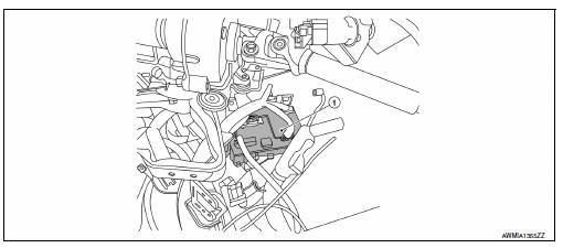
- Bcm (view with instrument panel removed)
Combination switch reading system
COMBINATION SWITCH READING SYSTEM : Component Parts Location
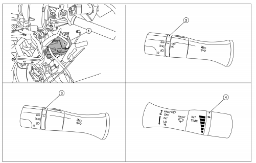
- BCM (view with combination meter removed)
- Combination switch (lighting and turn signal) (with fog lamps)
- Combination switch (lighting and turn signal) (without fog lamps)
- Combination switch (wiper and washer)
Power consumption control system
Power consumption control system : component parts location
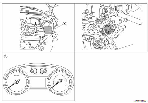
- Ipdm e/r
- Bcm (view with instrument panel removed)
- Combination meter
System
Body control system
Body control system : system description
Outline
- Bcm (body control module) controls various electrical components. It receives the information required from can communication and the signals received from each switch and sensor.
- Bcm has a combination switch reading function for reading the status of
combination switch (light, turn signal,
wiper and washer) in addition to functions for controlling the operation of
various electrical components.
It also has a signal transmission function for other systems, and a power consumption control function that reduces the power consumption with the ignition switch off.
- BCM is equipped with a diagnosis function that operates with CONSULT and allows for various settings to be changed.
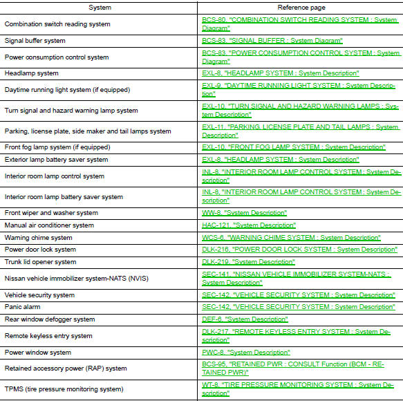
Bcm function list
Combination switch reading system
COMBINATION SWITCH READING SYSTEM : System Diagram
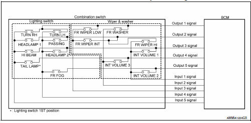
COMBINATION SWITCH READING SYSTEM : System Description
OUTLINE
- BCM reads the status of the combination switch (light, turn signal, wiper and washer) and recognizes the status of each switch.
- BCM has a combination of 5 output terminals (OUTPUT 1 - 5) and 5 input terminals (INPUT 1 - 5). It reads a maximum of 20 switch states.
COMBINATION SWITCH MATRIX
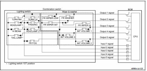
Combination switch circuit
Combination switch INPUT-OUTPUT system list


COMBINATION SWITCH READING FUNCTION
Description
- BCM reads the status of the combination switch at 10 ms intervals normally.
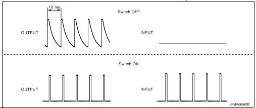
NOTE:
BCM reads the status of the combination switch at 60 ms intervals when BCM is controlled at low power consumption control mode.
BCM operates as follows and judges the status of the combination switch.
- It operates the transistor on OUTPUT side in the following order: OUTPUT 1 → 2 → 3 → 4 → 5, and outputs voltage waveform.
- The voltage waveform of OUTPUT corresponding to the formed circuit is input into the interface on INPUT side if any (1 or more) switches are ON.
- It reads this change of the voltage as the status signal of the combination switch.
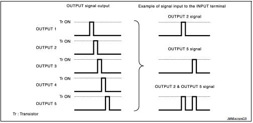
Operation Example
In the following operation example, the combination of the status signals of the combination switch is replaced as follows: INPUT 1 - 5 to “1 - 5” and OUTPUT 1 - 5 to “A - E”.
Example 1: When a switch (TAIL LAMP) is turned ON
- The circuit between OUTPUT 4 and INPUT 5 is formed when the TAIL LAMP switch is turned ON.
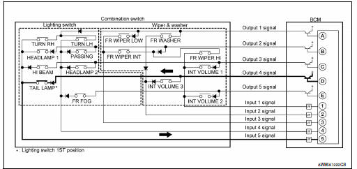
- BCM detects the combination switch status signal “5D” when the signal of OUTPUT 4 is input to INPUT 5.
- BCM judges that the TAIL LAMP switch is ON when the signal “5D” is detected.
Example 2: When some switches (TURN RH, TAIL LAMP) are turned ON
- The circuits between OUTPUT 1 and INPUT 5 and between OUTPUT 4 and INPUT 5 are formed when the TURN RH switch and TAIL LAMP switch are turned ON.
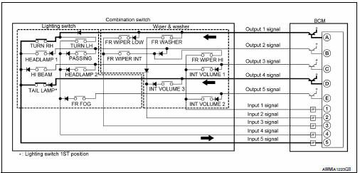
- BCM detects the combination switch status signal “5AD” when the signals of OUTPUT 1 and OUTPUT 4 are input to INPUT 5.
- BCM judges that the TURN RH switch and TAIL LAMP switch are ON when the signal “5AD” is detected.
Signal buffer
Signal buffer : system diagram
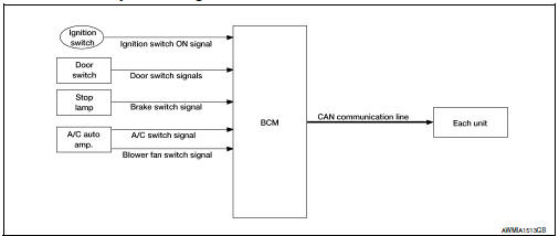
Signal buffer : system description
OUTLINE
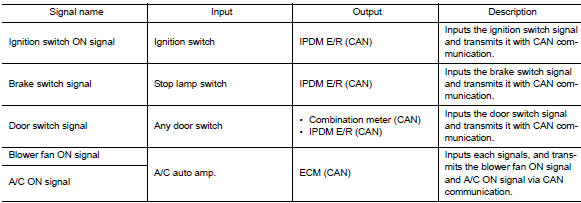
BCM has the signal transmission function that outputs/transmits each input/received signal to each unit.
SIGNAL TRANSMISSION FUNCTION LIST
Power consumption control system
Power consumption control system : system diagram
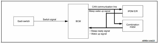
Power consumption control system : system description
OUTLINE
- BCM incorporates a power saving control function that reduces the power consumption according to the vehicle status.
- BCM switches the status (control mode) by itself with the power saving control function. It performs the sleep request to each unit (IPDM E/R and combination meter) that operates with the ignition switch OFF.
Normal mode (wake-up)
- CAN communication is normally performed with other units
- Each control with BCM is operating properly
CAN communication sleep mode (CAN sleep)
- CAN transmission is stopped
- Control with BCM only is operating
Low power consumption mode (BCM sleep)
- Low power consumption control is active
- CAN transmission is stopped
LOW POWER CONSUMPTION CONTROL WITH BCM
BCM reduces the power consumption with the following operation in the low power consumption mode.
- The reading interval of the switches changes from 10 ms interval to 60 ms interval.
Sleep mode activation
- BCM receives the sleep-ready signal (ready) from IPDM E/R and combination meter via CAN communication.
- BCM transmits the sleep wake up signal (sleep) to each unit when all of the CAN sleep conditions are fulfilled.
- Each unit stops the transmission of CAN communication with the sleep wake up signal. BCM is in CAN communication sleep mode
- BCM is in the low power consumption mode and performs the low power consumption control when all of the BCM sleep conditions are fulfilled with CAN sleep condition.
Sleep condition
| CAN sleep condition | BCM sleep condition |
|
|
Wake-up operation
- BCM transmits sleep wake up signal (wake up) to each unit when any condition listed below is established, and then goes into normal mode from low power consumption mode.
- Each unit starts transmissions with CAN communication by receiving sleep wake up signals. Each unit transmits wake up signals to BCM with CAN communication to convey the start of CAN communication.
Wake-up condition
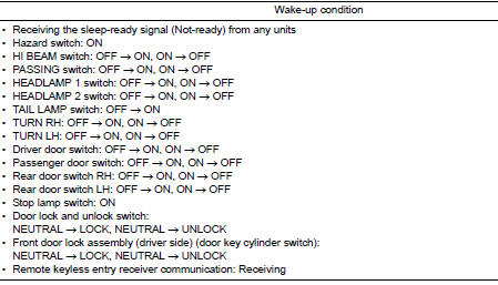
 Precaution
Precaution for supplemental restraint system (srs) "air bag" and "seat
belt pre-tensioner"
The supplemental restraint system such as “air bag” and “seat belt pre- ...
 Diagnosis system (bcm)
Common item
Common item : consult function (bcm - common item)
APPLICATION ITEM
CONSULT performs the following functions via CAN communication with BCM.
Direct Diagnostic Mode
Descriptio ...
Other materials:
Electrical units location
Electrical units location
Engine compartment
Passenger compartment
Luggage compartment
...
Parking brake shoe
Removal and Installation - Drum Brake
If equipped with drum brakes, refer to BR-42, "Removal and
Installation".
Exploded View - Disc Brake
Anti-rattle pin
Back plate
Toggle lever
Parking brake shoe
Brake strut
Return spring
Spring
Adjuster
...
Continuously Variable Transmission (CVT) (if so equipped)
WARNING
Do not depress the accelerator pedal
while shifting from P (Park) or N (Neutral)
to R (Reverse), D (Drive) or L (Low).
Always depress the brake pedal until
shifting is completed. Failure to do so
could cause you to lose control and
have an accident.
Col ...
