Nissan Sentra Service Manual: System description
Refrigeration system
Component part location
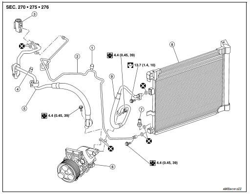
- High-pressure service port
- High-pressure pipe
- Expansion valve
- Low-pressure service port
- Low-pressure flexible hose
- Compressor
- Refrigerant pressure sensor
- Condenser and liquid tank assembly
- High-pressure flexible hose
Refrigerant cycle
Refrigerant flow
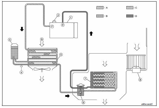
- Electric compressor
- Pressure relief valve
- Liquid tank
- Refrigerant pressure sensor
- Condenser
- Expansion valve
- Evaporator
- Blower motor
- High-pressure gas
- High-pressure liquid
- Low-pressure liquid
- Low-pressure gas
- Suction port
- Discharge port
- Outside air
Refrigerant Flow
The refrigerant from the compressor flows through the condenser and liquid tank, the evaporator and returns to the compressor. The refrigerant evaporation in the evaporator is controlled by an expansion valve.
Freeze Protection
To prevent the evaporator from freezing up, the evaporator air temperature is monitored by the intake sensor and the voltage signal to the A/C auto amp. makes the A/C relay go OFF and stop the compressor
Refrigerant system protection
Refrigerant pressure sensor
The refrigerant system is protected against excessively high or low pressures by the refrigerant pressure sensor, located on the liquid tank. If the system pressure rises above or falls below the specifications, the refrigerant pressure sensor detects the pressure inside the refrigerant line and sends the voltage signal to the ECM.
The ECM then ceases to supply power to the A/C relay which disengages and stops the compressor when pressure on the high pressure side (as detected by refrigerant pressure sensor) is over approximately 2,746 kPa (28 kg/cm2, 398 psi), or below approximately 120 kPa (1.22 kg/cm2, 17.4 psi).
Pressure Relief Valve
The refrigerant system is also protected by a pressure relief valve, located in the rear head of the compressor.
When the pressure of refrigerant in the system increases to an abnormal level [more than 3,727 kPa (38 kg/ cm2, 540 psi)], the release port on the pressure relief valve automatically opens and releases refrigerant into the atmosphere.
 Preparation
Special service tool
The actual shape of the tools may differ from those illustrated here.
HFC-134a (r-134a) service tool and equipmen.T.
Do not mix HFC-134a (R-134a) refrigerant and/or its s ...
 Basic inspection
Diagnosis and repair workflow
Workflow
OVERALL SEQUENCE
DETAILED FLOW
1.INTERVIEW CUSTOMER
Interview the customer to obtain as much information as possible about the
conditions and environm ...
Other materials:
Parking brake shoe
Adjustment - Drum Brake
If equipped with drum brakes, refer to PB-11, "Inspection and
Adjustment".
Adjustment - Disc Brake
Adjust parking brake lever stroke. Refer to PB-4,
"Inspection and Adjustment".
Perform parking brake break-in (drag on) operation by
d ...
Audio operation precautions
Compact disc (CD) player
CAUTION
Do not force a compact disc into the CD
insert slot. This could damage the CD
and/or CD player.
Trying to load a CD with the CD door
closed could damage the CD and/or CD
player.
Only one CD can be loaded into the CD
player at a time.
Only ...
Pregnant women
NISSAN recommends that pregnant women use
seat belts. The seat belt should be worn snug and
always position the lap belt as low as possible
around the hips, not the waist. Place the shoulder
belt over your shoulder and across your chest.
Never run the lap/shoulder belt over your abdominal
ar ...
