Nissan Sentra Service Manual: System
System Diagram
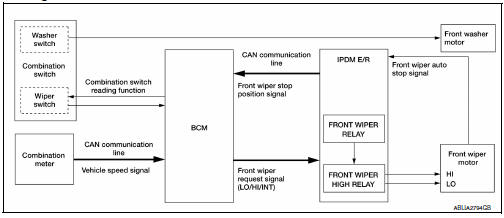
System Description
FRONT WIPER CONTROL (BASIC)
- BCM detects the combination switch position by the combination switch reading function.
- BCM transmits the front wiper request signal to the IPDM E/R using CAN communication.
- IPDM E/R controls the integrated front wiper relay and front wiper high relay based on the status of the front wiper request signal.
- IPDM E/R provides power to operate the front wiper motor.
LOW SPEED OPERATION
- Ignition switch ON.
- Front wiper switch in LO or MIST position.
- BCM reads the combination switch position and transmits the front wiper request signal (LO) to IPDM E/R using CAN communication.
- IPDM E/R turns ON the front wiper relay.
HIGH SPEED OPERATION
- Ignition switch ON.
- Front wiper switch in HI.
- BCM reads the combination switch position and transmits the front wiper request signal (HI) to IPDM E/R using CAN communication
- IPDM E/R turns ON the front wiper relay and the front wiper high relay.
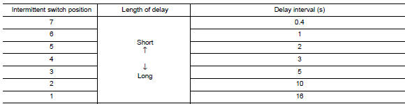
INTERMITTENT OPERATION
- Ignition switch ON.
- Front wiper switch INT.
- BCM reads the combination switch position. BCM calculates the delay interval based on the table below and then transmits the front wiper request signal (INT) to IPDM E/R using CAN communication.
- IPDM E/R turns ON the front wiper relay only once.
- BCM detects stop position of the front wiper motor based on the front wiper stop position signal received from the IPDM E/R.
- BCM transmits the front wiper request signal (INT) again after the delay interval.
AUTO STOP OPERATION
- Front wiper switch is turned OFF.
- BCM monitors wiper switch position by combination switch reading position function.
- BCM stops transmitting the front wiper request signal to the IPDM E/R.
- IPDM E/R detects the front wiper auto stop signal from the position of the front wiper motor (stop position/ except stop position).
- When the front wiper request signal is stopped, IPDM E/R turns ON the front wiper relay until the front wiper motor returns to the stop position
- IPDM E/R turns the front wiper relay OFF when the front wiper motor has reached the stop position.
MIST OPERATION
- Ignition switch ON.
- Front washer switch in OFF position.
- Front wiper switch in MIST position.
- BCM reads the combination switch position and transmits the front wiper request signal (LO) to IPDM E/R using CAN communication.
- IPDM E/R turns ON the front wiper relay.
- The front wiper operates once after the front washer operation.
WIPER/WASHER OPERATION
- Ignition switch ON.
- Front washer switch ON.
- The front washer switch provides ground for the front washer motor.
- BCM reads the combination switch position and transmits the front wiper request signal (LO) to IPDM E/R using CAN communication.
- BCM transmits the front wiper request signal (LO) to IPDM E/R using CAN communication.
- IPDM E/R turns ON the front wiper relay.
- The front wiper operates.
NOTE:
BCM transmits the front wiper request signal (LO) so that the front wiper operates approximately 3 times after front washer switch OFF is detected.
Fail-Safe
FAIL−SAFE OPERATION
IPDM E/R performs the fail-safe function when the front wiper auto stop circuit is malfunctioning. Refer to PCS-19, "Fail-safe" (with Intelligent Key system) or PCS-47, "Fail-Safe" (without Intelligent Key system).
 Front wiper and washer system
Component Parts Location
BCM (view under instrument panel,
left side of vehicle)
Combination meter
IPDM E/R (view with air inlet duct
removed)
Combination switch (wiper and
washer ...
 Diagnosis system (bcm) (with intelligent key system)
Common item
Common item : consult function (bcm - common item)
APPLICATION ITEM
CONSULT performs the following functions via CAN communication with BCM.
SYSTEM APPLICATION
BCM can perform the ...
Other materials:
Owner’s Manual/Service Manual order information
Genuine NISSAN Service Manuals for this model
year and prior can be purchased. A genuine
NISSAN Service Manual is the best source of
service and repair information for your vehicle.
This manual is the same one used by the factorytrained
technicians working at NISSAN dealerships.
Genuine NI ...
Timing chain
Exploded View
Timing chain slack guide
Timing chain tensioner
Timing chain
Oil pump drive chain
Crankshaft sprocket
Crankshaft key
Oil pump sprocket
Front cover
O-ring
O-ring
Valve timing control solenoid valve cover
O-ring
Valve timing control solenoid valve
(EXH)
...
Symptom diagnosis
CVT CONTROL SYSTEM
Symptom Table
The diagnosis item number indicates the order of check. Start checking in the
order from 1.
...
