
Nissan Sentra Service Manual: System
System Diagram
FRONT POWER WINDOW LH ANTI-PINCH SYSTEM
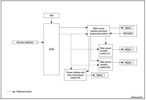
System Description
MAIN POWER WINDOW AND DOOR LOCK/UNLOCK SWITCH INPUT/OUTPUT SIGNAL CHART
| Item | Input signal to main power window and door lock/unlock switch | Main power window and door lock/unlock switch function | Actuator |
| Encoder | Encoder pulse signal | Power window control | Front power window motor |
| Main power window and door lock/unlock switch | Front power window motor LH UP/ DOWN signal | ||
| Power window and door lock/unlock switch RH | Front power window motor RH UP/ DOWN signal | ||
| BCM | RAP signal | Rear power window motor | |
| Rear power window switch | Rear power window motor UP/DOWN signal |
POWER WINDOW OPERATION
- Power window system is activated by the power window switch when the ignition switch is in the ON position or during the retained power operation after ignition switch is turned OFF.
- Main power window and door lock/unlock switch can open/close all windows.
- Front & rear power window switches can open/close the corresponding windows.
- Power window lock switch can lock all power windows other than driver seat.
- If door glass receives resistance that is more than the specified value and the power window is in the AUTOUP operation (Front LH), power window will move in the reverse direction (Anti-Pinch Function).
POWER WINDOW AUTO-OPERATION (FRONT LH)
- AUTO UP/DOWN operation can be performed when main power window and door lock/unlock switch turns to AUTO.
- Encoder continues detecting the movement of power window motor and transmits to main power window and door lock/unlock switch as the encoder pulse signal while power window motor is operating.
- Main power window and door lock/unlock switch reads the changes of encoder signal and stops AUTO operation when door glass is at fully opened/closed position.
- Power window motor is operable in case encoder is malfunctioning.
RETAINED POWER OPERATION
- Retained power operation is an additional power supply function that enables power window system to operate during the 45 seconds even when ignition switch is turned OFF
Retained power function cancel conditions
- Front door CLOSE (door switch OFF)→OPEN (door switch ON).
- When ignition switch is ON.
- When timer time passes. (45 seconds)
- AUTO function does not operate if encoder is malfunctioning.
POWER WINDOW LOCK FUNCTION
Ground circuit inside main power window and door lock/unlock switch shuts off when power window lock switch is ON. This inhibits power window switch operation except with the main power window and door lock/ unlock switch.
ANTI-PINCH OPERATION (FRONT LH)
- Pinch foreign material in the door glass during AUTO-UP operation, and it is the anti-pinch function that lowers the door glass 150mm. (5.9 in.) or 2 seconds when detected.
- Encoder continues detecting the movement of power window motor and transmits to main power window and door lock/unlock switch as the encoder pulse signal while power window motor is operating.
- Resistance is applied to the power window motor rotation that changes the frequency of encoder pulse signal if foreign material is trapped in the door glass.
- Power window switch controls to lower the window glass form 150mm (5.9 in.) or 2 seconds after it detects encoder pulse signal frequency change.
OPERATION CONDITION
- When door glass AUTO-UP operation is performed (anti-pinch function does not operate just before the door glass closes and is fully closed)
NOTE:
Depending on environment and driving conditions, if a similar impact or load is applied to the door glass, it may lower.
Fail-safe
FAIL-SAFE CONTROL
Switches to fail-safe control when malfunction is detected in the encoder signal that detects UP/DOWN speed and direction of door glass. Switches to fail-safe control when an error beyond the regulation value is detected between the fully closed position and the actual position of the glass.
| Malfunction | Malfunction condition |
| Pulse sensor malfunction | When only one side of pulse signal is being detected for more than the specified value. |
| Both pulse sensors malfunction | When both pulse signals have not been detected for more than the specified value during glass open/close operation. |
| Pulse direction malfunction | When the pulse signal that is detected during glass open/close operation detects the opposite condition of power window motor operating direction. |
| Glass recognition position malfunction 1 | When it detects the error between glass fully closed position in power window switch memory and actual fully closed position during glass open/close operation is more than the specified value. |
| Glass recognition position malfunction 2 | When it detects pulse count more that the value of glass full stroke during glass open/close operation. |
| Malfunction of not yet updated closed position of glass | When glass open/close operation is continuously performed without fully closing more that the specified value (approximately 10 strokes). |
It changes to condition before initialization and the following functions do not operate when switched to failsafe control:
- Auto-up operation
- Anti-pinch function
- Retained power function
Perform initial operation to recover when switched to fail-safe mode. However, it switches back to fail-safe control when malfunction is found in power window switch or in motor.
Diagnosis system (bcm) (with intelligent key system)
Common item
COMMON ITEM : CONSULT Function (BCM - COMMON ITEM)
APPLICATION ITEM
CONSULT performs the following functions via CAN communication with BCM.
| Direct Diagnostic Mode | Description |
| ECU identification | The BCM part number is displayed. |
| Self Diagnostic Result | The BCM self diagnostic results are displayed. |
| Data Monitor | The BCM input/output data is displayed in real time. |
| Active Test | The BCM activates outputs to test components. |
| Work support | The settings for BCM functions can be changed. |
| Configuration |
|
| CAN DIAG SUPPORT MNTR | The result of transmit/receive diagnosis of CAN communication is displayed. |
SYSTEM APPLICATION
BCM can perform the following functions.
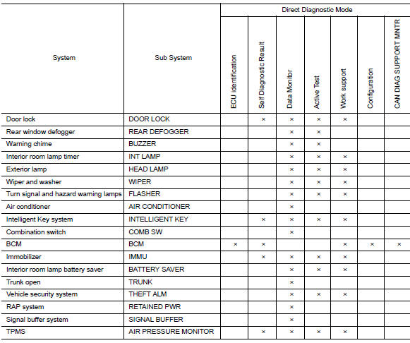
Retained pwr
RETAINED PWR : CONSULT Function (BCM - RETAINED PWR)
DATA MONITOR

Diagnosis system (bcm) (without intelligent key system)
Common item
COMMON ITEM : CONSULT Function (BCM - COMMON ITEM)
APPLICATION ITEM
CONSULT performs the following functions via CAN communication with BCM.
| Direct Diagnostic Mode | Description |
| ECU identification | The BCM part number is displayed. |
| Self Diagnostic Result | The BCM self diagnostic results are displayed. |
| Data Monitor | The BCM input/output data is displayed in real time. |
| Active Test | The BCM activates outputs to test components. |
| Work support | The settings for BCM functions can be changed. |
| Configuration |
|
| CAN DIAG SUPPORT MNTR | The result of transmit/receive diagnosis of CAN communication is displayed. |
SYSTEM APPLICATION
BCM can perform the following functions.
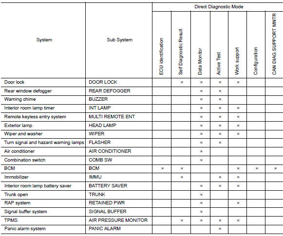
Retained pwr
RETAINED PWR : CONSULT Function (BCM - RETAINED PWR)
DATA MONITOR

WORK SUPPORT

*: Initial setting
 Component parts
Component Parts Location
BCM (view under instrument panel
on the left side of the vehicle)
Front power window motor LH (RH
similar) (view with front door finisher
removed)
Rear powe ...

Other materials:
P1800 Intake manifold tuning valve
DTC Logic
DTC DETECTION LOGIC
DTC No.
CONSULT screen terms
(Trouble diagnosis content)
DTC detecting condition
Possible cause
P1800
VIAS S/V-1
(Variable intake air system control
solenoid valve-1)
An excessively low or high voltage signal
is sent to ECM t ...
Precaution for Seat Belt Service
CAUTION:
Before removing the seat belt pre-tensioner assembly, turn the
ignition switch OFF, disconnect both
battery terminals and wait at least three minutes. For approximately three
minutes after the battery
terminals have been removed, it is still possible for the air bag and seat
...
Main line between ipdm-e and dlc circuit
Diagnosis procedure
1.Check connector
Turn the ignition switch OFF.
Disconnect the battery cable from the negative terminal.
Check the following terminals and connectors for damage, bend and loose
connection (connector side
and harness side).
Harness connector E4
Harness connec ...
