Nissan Sentra Service Manual: Component parts
Component Parts Location
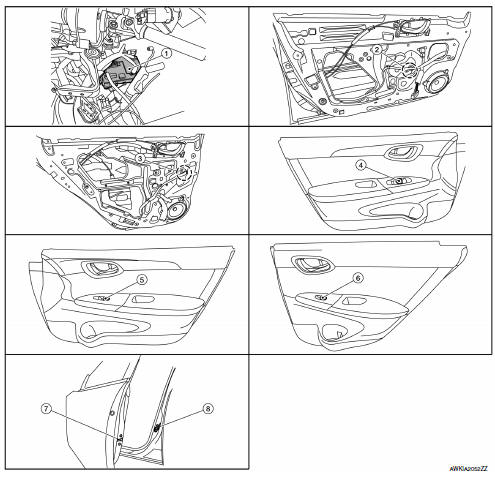
- BCM (view under instrument panel on the left side of the vehicle)
- Front power window motor LH (RH similar) (view with front door finisher removed)
- Rear power window motor LH (RH similar) (view with rear door finisher removed)
- Main power window and door lock/ unlock switch
- Power window and door lock/unlock switch RH
- Rear power window switch RH (LH similar)
- Front door lock assembly LH (key cylinder switch)
- Front door switch LH (RH similar)
Component Description
FRONT POWER WINDOW LH ANTI-PINCH SYSTEM
| Component | Function |
| BCM |
|
| Front power window motor LH |
|
| Front power window motor RH | Starts operating with signals from main power window and door lock/unlock switch & power window and door lock/unlock switch RH. |
| Main power window and door lock/unlock switch |
|
| Power window and door lock/unlock switch RH | Controls front power window motor RH. |
| Rear power window switch | Controls rear power window motors LH and RH. |
| Rear power window motor | Starts operating with signals from main power window and door lock/unlock switch & rear power window switch. |
| Front door switch LH or RH | Detects door open/close condition and transmits to BCM. |

 System
System Diagram
FRONT POWER WINDOW LH ANTI-PINCH SYSTEM
System Description
MAIN POWER WINDOW AND DOOR LOCK/UNLOCK SWITCH
INPUT/OUTPUT SIGNAL CHART
Item
Input signal to main power win ...
Other materials:
Abbreviations
Abbreviation List
The following ABBREVIATIONS are used:
A
ABBREVIATION
DESCRIPTION
A/C
Air conditioner
A/C
Air conditioning
A/F sensor
Air fuel ratio sensor
A/T
Automatic transaxle/transmission
ABS
Anti-lock braking sys ...
Preparation
Special service tools
The actual shape of the tools may differ from those illustrated here.
Commercial service tools
Clip list
Descriptions for Clips
Replace any clips which are damaged during removal or installation.
...
Rear door
Door assembly
Door assembly : removal and installation
Caution:
Use two people when removing or installing the rear door assembly
due to its heavy weight.
When removing and installing rear door assembly, support rear door
with a suitable tool.
Removal
Remove rear door assembly h ...
