Nissan Sentra Service Manual: Steering knuckle
Exploded View
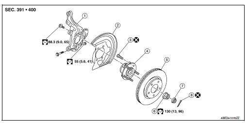
- Steering knuckle
- Splash guard
- Wheel stud
- Wheel hub and bearing
- Disc brake rotor
- Wheel hub lock nut
- Nut retainer
- Cotter pin
Removal and Installation
REMOVAL
- Remove the wheel and tire using power tool. Refer to WT-47, "Exploded View".
- Remove the nut and disconnect the steering outer socket from the steering knuckle. Refer to ST-14, "Removal and Installation".
- Remove the nut and bolt from the lower ball joint. Disconnect the steering knuckle from the transverse link.
- Remove the wheel hub and bearing from the steering knuckle. Refer to FAX-8, "Removal and Installation".
- Remove the splash guard from the steering knuckle.
- Suspend the drive shaft with suitable wire.
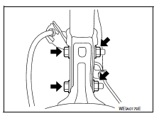
- Remove the lower strut nuts and bolts (

). Refer to FSU-8, "Exploded View".
- Remove the steering knuckle.
- Inspect the components. Refer to FSU-15, "Inspection".
INSTALLATION
Installation is in the reverse order of the removal.
CAUTION:
Do not reuse cotter pin.
- Complete the inspection. Refer to FSU-15, "Inspection".
Inspection
INSPECTION AFTER REMOVAL
Check the following items, and replace the part if necessary.
- Check components for deformation, cracks, and other damage.
- Check boots of transverse link and steering outer socket ball joint for breakage, axial end play, and swing torque.
- Transverse link: Refer to FSU-10, "Inspection".
- Steering outer socket: Refer to ST-8, "Inspection".
INSPECTION AFTER INSTALLATION
- Check the wheel sensor harness to be sure the connectors are fully seated.
- Check the wheel alignment. Refer to FSU-6, "Inspection".
 Front stabilizer
Exploded View
Stabilizer bar
Stabilizer clamp
Stabilizer bushing
Stabilizer connecting rod
Front coil spring and strut
Front suspension member
Front
Removal and Installation
RE ...
 Unit removal and installation
Front suspension member
Exploded View
Upper link
Front suspension member
Member stay
Front
Upper link
Front suspension member
Member stay
Front
Removal and Installat ...
Other materials:
P0128 Thermostat function
DTC Logic
DTC DETECTION LOGIC
NOTE:
If DTC P0128 is displayed with DTC P0300, P0301, P0302, P0303 or P0304,
first perform the trouble
diagnosis for P0300, P0301, P0302, P0303 or P0304. Refer to EC-269, "DTC Logic".
Engine coolant temperature has not risen enough to open the thermost ...
Door switch
With intelligent key
WITH INTELLIGENT KEY : Component Function Check
1.Check function
Select DOOR LOCK of BCM using CONSULT.
Select DOOR SW-DR, DOOR SW-AS, DOOR SW-RL and DOOR SW-RR in DATA MONITOR
mode.
Check that the function operates normally according to the following
conditions ...
P0846 Transmission fluid pressure SEN/SW B
DTC Logic
DTC DETECTION LOGIC
DTC
CONSULT screen terms
(Trouble diagnosis content)
DTC detection condition
Possible causes
P0846
TRANSMISSION FLUID
PRESSURE SEN/SW B
(Transmission Fluid Pressure
Sensor/Switch B Circuit
Range/Performance)
The detection ...
