Nissan Sentra Owners Manual: Speedometer and odometer
Speedometer
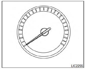
The speedometer indicates the vehicle speed.
Odometer/Twin trip odometer
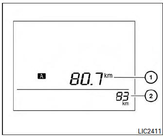
The odometer 2 and the twin trip odometer 1 are displayed when the ignition switch is placed in the ON position.
The odometer records the total distance the vehicle has been driven.
The twin trip odometer records the distance of individual trips.
To switch between the odometer and the twin trip
odometers press the  button on the
steering
wheel.
Changing the display:
Push the button on the steering
wheel to
change the display as follows:
Accel guide/Average fuel economy→Instant fuel
economy/Average fuel economy → Average fuel
economy→Average speed→Distance to empty
→ Trip A → Trip B
Resetting the trip odometer:
Push the  button on the steering
wheel for
more than 1 second to reset the currently displayed
trip odometer to zero.
Loose fuel cap warning message
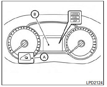
Push the reset button A for more than 1 second to reset the LOOSE FUEL CAP warning message B after the fuel cap has been tightened.
For additional information see “Fuel-filler cap” in the “Pre-driving checks and adjustments” section of this manual.
Check tire pressure warning message
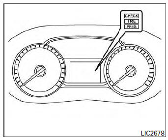
The CHECK TIRE PRES warning message is displayed when the low tire pressure warning light is illuminated and low tire pressure is detected.
Check and adjust the tire pressure to the recommended COLD tire pressure shown on the Tire and Loading Information label. The CHECK TIRE PRES warning message turns off when the low tire pressure warning light turns off.
The low tire pressure warning light remains illuminated until the tires are inflated to the recommended COLD tire pressure. The CHECK TIRE PRES warning message is displayed each time the ignition switch is placed in the ON position as long as the low tire pressure warning light remains illuminated. For more information see “Low tire pressure warning light” in the “Instruments and controls” section, “Tire Pressure Monitoring System (TPMS)” in the “Starting and driving” and “Wheels and tires” section in the “Maintenance and do-it-yourself” section of this Owner’s Manual.
 Meters and gauges
Engine coolant temperature gauge
Fuel gauge
Speedometer
Odometer/twin trip odometer/trip
computer/fuel economy/Eco Pedal Indicator
Tachometer
...
 Tachometer
The tachometer indicates engine speed in revolutions
per minute (rpm). Do not rev engine into
the red zone 1 .
CAUTION
When engine speed approaches the red
zone, reduce engine speed. Operating ...
Other materials:
NISSAN Intelligent Key® (if so equipped)
Your vehicle can only be driven with the Intelligent
Keys which are registered to your vehicle’s Intelligent
Key components and NISSAN Vehicle Immobilizer
System components.
Never leave these keys in the vehicle.
As many as 4 Intelligent Keys can be registered
and used with one vehicle. The ...
Ipdm-e branch line circuit
Diagnosis procedure
1.Check connector
Turn the ignition switch OFF.
Disconnect the battery cable from the negative terminal.
Check the terminals and connectors of the IPDM E/R for damage, bend and
loose connection (unit side
and connector side).
Is the inspection result normal?
Yes ...
Oil pan
Exploded View
O-ring
Oil pan (upper)
Oil level gauge guide
O-ring
Oil level gauge
Oil pump drive chain
Crankshaft sprocket
Oil pump sprocket
Oil pump chain tensioner
Oil pump
Drain plug
Drain plug washer
Oil pan (lower)
Oil filter
Clamp
Water hose
Oil cooler
...
