Nissan Sentra Service Manual: Removal and installation
Combination meter
Exploded view
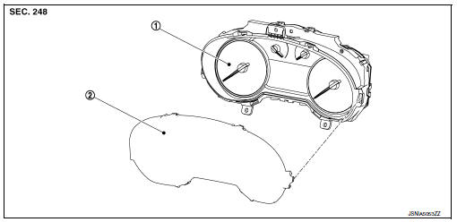
- Combination meter
- Front cover
Removal and installation
Removal
- Remove cluster lid a. Refer to ip-19, "removal and installation".
- Remove the screws from the combination meter.
- Remove the combination meter.
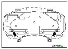
- Disconnect the combination meter harness connector and remove.
Installation
Installation is in the reverse order of removal.
Disassembly and assembly
Disassembly
Caution:
- Do not touch the display, pointer, the inside of front cover and the printed area of the dial during the work.
- Keep away from magnetic sources.
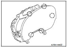
- Release the pawls and remove the front cover.
 Pawl
Pawl
Assembly
Assembly is in the reverse order of disassembly.
Caution:
- Do not touch the display, pointer, the inside of front cover and the printed area of the dial during the work.
- Keep away from magnetic sources.
Steering switch
Removal and installation
For removal and installation of the steering switch, refer to AV-62, "Removal and Installation".
Illumination control switch
Removal and installation
For removal and installation of the illumination control switch refer to inl-57, "removal and installation".
 Normal operating condition
Compass
Compass : description
Compass
The electronic compass is highly protected from changes in most magnetic
fields. However, some large
changes in magnetic fields can affect it. Some exa ...

Other materials:
Precaution for Brake Control System
Always perform a pre-driving check to drive the vehicle.
Always check speed and safety while driving the vehicle.
To operate CONSULT while driving, more than one person is
required to be in the vehicle to avoid interference
to driving and ensure safety.
Slight vibrations ar ...
System description
Component parts
Body control system
Body control system : component parts location
BCM (view with instrument panel removed)
Combination switch reading system
Combination switch reading system : component parts location
BCM (view with combination meter
removed)
Combination s ...
P285A Clutch B Pressure
DTC Logic
DTC DETECTION LOGIC
DTC
CONSULT screen terms
(Trouble diagnosis content)
DTC detection condition
Possible causes
P285A
CLUTCH B PRESSURE
(Clutch B Pressure Disengagement
Performance)
The detection conditions continuously for 200
msec or more und ...
