
Nissan Sentra Service Manual: Rear disc brake
Exploded View
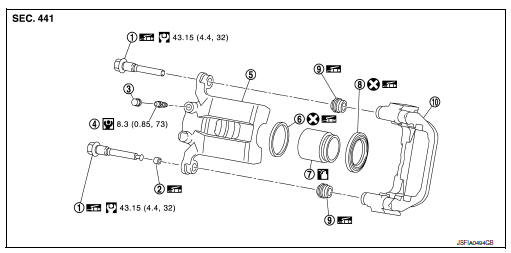
- Sliding pin bolt
- Bushing
- Cap
- Bleeder valve
- Cylinder body
- Piston seal
- Piston
- Piston boot
- Sliding pin boot
- Torque member
 Apply rubber grease
 Apply brake fluid
Disassembly and Assembly
DISASSEMBLY
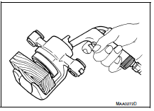
- Place a wooden block as shown, and blow air from union bolt hole to remove piston and piston boot.
WARNING:
Do not get fingers caught between piston and cylinder body.
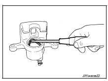
- Remove piston seal from cylinder body using suitable tool.
CAUTION:
Do not damage cylinder inner wall.
- Remove bleeder valve and cap.
ASSEMBLY
- Install bleeder valve and cap.
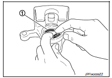
- Apply rubber grease to piston seal (1), and install to cylinder body.
CAUTION:
Do not reuse piston seal.
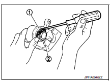
- Apply rubber grease to piston boot (1). Cover the piston (2) end with piston boot, and install cylinder side lip on piston boot securely into a groove on cylinder body.
CAUTION:
Do not reuse piston boot.
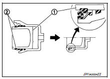
- Apply new brake fluid to piston (1). Push piston into cylinder body by hand and push piston boot (2) piston-side lip into the piston groove.
CAUTION:
Press the piston evenly and vary the pressing point to prevent cylinder inner wall from being rubbed.
 Rear drum brake
Exploded View
Cap
Bleeder valve
Piston
Spring
Boot
Piston cup
Wheel cylinder
Apply rubber grease
Apply PBC (Poly Butyl Cuprysil)
grease or silicone-based grease
Apply ...
 Service data and specifications (SDS)
General Specifications
Brake Pedal
Check Valve
Brake Booster
Front Disc Brake
Rear Drum Brake
Rear Disc Brake
...
Other materials:
Precaution
Precaution for Supplemental Restraint System (SRS) "AIR BAG" and "SEAT
BELT PRE-TENSIONER"
The Supplemental Restraint System such as “AIR BAG” and “SEAT BELT PRE-TENSIONER”,
used along
with a front seat belt, helps to reduce the risk or severity of injur ...
Intake valve timing control
INTAKE VALVE TIMING CONTROL : System Description
SYSTEM DIAGRAM
INPUT/OUTPUT SIGNAL CHART
Sensor
Input signal to ECM
ECM function
Actuator
Crankshaft position sensor (POS)
Engine speed and piston position
Intake valve timing
control
Intake valve timing con ...
The key warning does not sound
(without intelligent key)
Description
The key warning chime does not sound, when all of the following conditions
are fulfilled.
Key inserted into the key cylinder (key switch signal on).
Ignition switch is in acc or off (ignition switch signal off).
Driver side door is open (driver side door switch on)
Diagnosi ...
