Nissan Sentra Service Manual: Parking brake system
Inspection and Adjustment
INSPECTION
Lever Stroke
-
Operate the parking brake lever with a force of 196 N (20.0 kg-f, 44.1 lb-f). Check that the lever stroke is within the specified number of notches. (Check it by listening to the clicks of the ratchet.)
Number of notches : Refer to PB-13, "Parking Brake Control".
-
When brake warning lamp turns ON, check that the lever stroke is within the specified number of notches.
(Check it by listening to the clicks of the ratchet.)
Number of notches : Refer to PB-13, "Parking Brake Control".
Inspect Components
-
Make sure that the attachment conditions (looseness, backlash, etc.) of each component are normal.
-
Check the following:
-
Device assembly for bends, damage and cracks. Replace if any damage is noted.
-
Cables and equalizer for wear and damage. Replace if any damage is noted.
-
Parking brake switch. Replace if it does not work correctly.
ADJUSTMENT - Drum Brakes
-
Remove center console cup holder finisher. Refer to IP-17, "Exploded View".
-
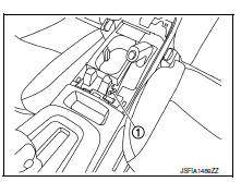
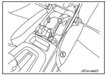
Engage parking brake lever, then lift up the end of the trim on the parking brake lever to access the adjusting nut.
-
Insert a suitable tool onto adjusting nut (1). Rotate adjusting nut to fully loosen cable, and then release parking brake lever.
-
Depress the foot brake about 10 times and adjust the rear shoe clearance.
CAUTION:
Be sure to securely depress the foot brake.
-
Rotate brake drum to make sure that there is no drag.
-
Adjust parking brake cable with the following procedure.
-
When replace parking brake cable, operate parking brake lever with a force of 400 N (40.8 kg-f, 89.9 lb-f) about 10 times.
-
Engage parking brake lever, then lift up the end of the trim on the parking brake lever to access the adjusting nut.
-
Rotate adjusting nut to adjust parking brake lever stroke using suitable tool.
-
Operate parking brake lever with a force of 196 N (20.0 kg-f, 44.1 lb-f), make sure the parking brake lever stroke is within the specified number of notches. (Check it by listening and counting ratchet clicks.)
Number of notches Refer to PB-13, "Parking Brake Control".
-
Make sure that there is no drag on rear brake with parking brake lever completely released.
-
Install center console cup holder finisher. Refer to IP-17, "Exploded View".
ADJUSTMENT - Disc Brakes
-
Remove rear wheels and tires using power tool. Refer to WT-47, "Adjustment".
-
Secure both disc rotors to wheel hubs using wheel nuts.
-
Remove the adjusting hole plug from the disc rotor. Turn the adjuster (1) in the direction (A) as shown using suitable tool until the disc rotor is locked.
-
Turn back the adjuster 7 notches from the locked position.
-
Rotate the disc rotor to check that there is no drag. Install the adjuster hole plug. Refer to PB-11, "Inspection and Adjustment"
-
Adjust the cable with the following procedure.
-
Operate the parking brake lever with a force of 400 N (40.8 kg-f, 89.9 lb-f) for 10 strokes or more.
-
Remove center console cup holder finisher. Refer to IP-17, "Exploded View".
-
Insert suitable tool onto adjusting nut (1). Adjust the parking brake lever stroke by turning the adjusting nut (1).
CAUTION:
Make sure to securely depress the brake pedal.
-
Operate the parking brake lever with a force of 196 N (20.0 kg-f, 44.1 lb-f). Check that the parking brake lever stroke is within the specified number of notches. (Check it by listening to the clicks of the ratchet.)
Number of notches : Refer to PB-13, "Parking Brake Control".
-
Rotate the disc rotor to check that there is no drag. Refer to PB-11, "Inspection and Adjustment".
-
Install center console cup holder finisher. Refer to IP-17, "Exploded View".
 Basic inspection
...
 Parking brake shoe
Adjustment - Drum Brake
If equipped with drum brakes, refer to PB-11, "Inspection and
Adjustment".
Adjustment - Disc Brake
Adjust parking brake lever stroke. Refer to PB-4,
&q ...
Other materials:
C1105, C1106, C1107, C1108 Wheel sensor
Description
When the sensor rotor rotates, the magnetic field changes. It
converts the magnetic field changes to current
signals (rectangular wave) and transmits them to the ABS actuator and electric
unit (control unit).
DTC Logic
DTC DETECTION LOGIC
DTC
Display Item
Malfunct ...
Readiness for inspection/maintenance (I/M) test
Due to legal requirements in some states and
Canadian Provinces, your vehicle may be required
to be in what is called the “ready condition”
for an Inspection/Maintenance (I/M) test of
the emission control system.
The vehicle is set to the “ready condition” when it
is driven through c ...
Air conditioner system refrigerant and oil recommendations
The air conditioner system in your NISSAN
vehicle must be charged with the refrigerant
HFC-134a (R-134a) and NISSAN A/C
system oil Type S or the exact equivalents.
CAUTION
The use of any other refrigerant or oil will
cause severe damage to the air conditioning
system and will require the repl ...
