Nissan Sentra Service Manual: P2118 Throttle control motor
DTC Logic
DTC DETECTION LOGIC
| DTC No. | CONSULT screen terms (Trouble diagnosis content) | DTC detecting condition | Possible cause |
| P2118 | ETC MOT-B1 (Throttle actuator control motor current range/ performance) | ECM detects short in both circuits between ECM and throttle control motor. |
|
DTC CONFIRMATION PROCEDURE
1.PRECONDITIONING
If DTC Confirmation Procedure has been previously conducted, always perform the following procedure before conducting the next test.
- Turn ignition switch OFF and wait at least 10 seconds.
- Turn ignition switch ON.
- Turn ignition switch OFF and wait at least 10 seconds.
>> GO TO 2.
2.PERFORM DTC CONFIRMATION PROCEDURE
- Turn ignition switch ON and wait at least 2 seconds.
- Start engine and let it idle for 5 seconds.
- Check DTC.
Is DTC detected? YES >> Proceed to EC-428, "Diagnosis Procedure".
NO >> INSPECTION END
Diagnosis Procedure
1.CHECK THROTTLE CONTROL MOTOR OUTPUT SIGNAL CIRCUIT
- Turn ignition switch OFF.
- Disconnect electric throttle control actuator harness connector.
- Disconnect ECM harness connector
- Check the continuity between electric throttle control actuator harness connector and ECM harness connector.
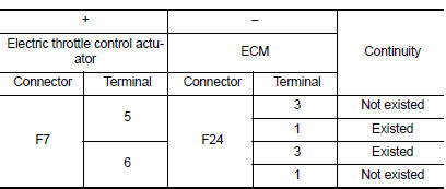
- Also check harness for short to ground and to power.
Is the inspection result normal? YES >> GO TO 2.
NO >> Repair or replace error-detected parts.
2.CHECK THROTTLE CONTROL MOTOR
Check the throttle control motor. Refer to EC-429, "Component Inspection (Throttle Control Motor)".
Is the inspection result normal? YES >> Check intermittent incident. Refer to GI-39, "Intermittent Incident".
NO >> Replace electric throttle control actuator. Refer to EM-27, "Removal and Installation".
Component Inspection (Throttle Control Motor)
1.CHECK THROTTLE CONTROL MOTOR
- Turn ignition switch OFF.
- Disconnect electric throttle control actuator harness connector.
- Check the resistance between electric throttle control actuator terminals as per the following.
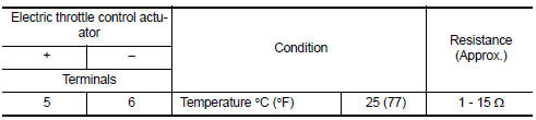
Is the inspection result normal? YES >> INSPECTION END
NO >> Replace electric throttle control actuator. Refer to EM-27, "Removal and Installation".
 P2101 Electric throttle control function
DTC Logic
DTC DETECTION LOGIC
NOTE:
If DTC P2101 is displayed with DTC P2100, first perform the trouble
diagnosis for DTC P2100. Refer
to EC-423, "DTC Logic".
If DTC P2101 is di ...
 P2119 Electric throttle control actuator
DTC Logic
DTC DETECTION LOGIC
DTC No.
CONSULT screen terms
(Trouble diagnosis content)
DTC detecting condition
Possible cause
P2119
ETC ACTR-B1
(Throttle actuator c ...
Other materials:
Precaution for supplemental restraint system (SRS) "air bag" and "seat belt
pre-tensioner"
The Supplemental Restraint System such as “AIR BAG” and “SEAT BELT PRE-TENSIONER”,
used along
with a front seat belt, helps to reduce the risk or severity of injury to the
driver and front passenger for certain
types of collision. Information necessary to service the system ...
Component parts
Component Parts Location
ABS actuator and electric unit (control
unit)
IPDM E/R
Brake fluid level switch
Front wheel sensor LH (RH similar)
Rear wheel sensor LH (RH similar)
VDC OFF switch
Steering angle sensor
(view with steering wheel removed)
Sto ...
Precaution for supplemental restraint system (srs) "air bag" and "seat belt
pre-tensioner"
The supplemental restraint system such as “air bag” and “seat belt pre-tensioner”,
used along
with a front seat belt, helps to reduce the risk or severity of injury to the
driver and front passenger for certain
types of collision. Information necessary to service the system ...
